Download
1 / 13
130 likes | 130 Vues
This research paper discusses the use of Chirped AM Ladar technology for range and Doppler measurements, as well as 3-D imaging. It includes a block diagram of the system, measurement theory, and field test results.

E N D
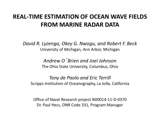
Chirped Amplitude Modulation Ladar for Range and Doppler Measurements and 3-D Imaging Barry Stann, Brian Redman, William Lawler, Mark Giza, John Dammann, Army Research Laboratory Dr. Keith Krapels, Office of Naval Research SPIE Defense & Security Symposium April 2007 The work presented here was jointly sponsored by CDR Keith Krapels, Ph.D., Office of Naval Research, and the Army Research Laboratory.
ONR Ladar Concepts of Employment Cruise Missile Tracking Coarse Range: Range-Doppler Tracking: 3D Imaging for Force Protection Coarse Range: 3D Imaging:
Chirped AM Range-Doppler Measurement Theory Frequency Transmitted/LO fIF Received fstop fD Dt fstart Time Tchirp Intermediate Frequency (IF) Signals for Each Chirp 2D FFT Slow Time = Chirp-to-Chirp
ONR Ladar Field Test Setup at CBD 256X256X256 Image at 295 m Range-Velocity Plot (V=1.566 m/s, Range=2.166 km)
ONR Advanced Breadboard Ladar (2006) High Power Long Pulse EDFA • Erbium amplifier contract start delayed • Image tube wore-out before October field test at Fort A.P. Hill • New field test planned with new image tube and high power EDFA when available
FOPEN Breadboard Ladar • NVESD foliage penetration data collection • Military targets • Ground-to-ground • Multi-aspect • 100 m range • FOPEN breadboard ladar • 1.55 µm, 1 W diode laser • 31 mm receiver aperture • 100m range • 128x128x128 Image • 1 s frame time • .5 m range resolution
FOPEN Ladar Illuminator Laser • Quintessence Photonics Diode Laser • 1550 nm • 1 W • Single transverse mode • Separate Osc./Amp. Sections facilitate modulation • Amp. Section < 4 A • Osc. Section < .7 A • Efficiency > 20 % Osc. driver RF amp. • Illuminator Characteristics • Modulated Output Power ~ .7 W • Bandwidth = 440 MHz • Buck converters for TE cooler and Oscillator drivers • 1 W Mini-Circuits Amp drives oscillator • RF Drive = 4-5 mW TE cooler driver
ONR/FOPEN Breadboard Components • Frequency synthesizer: • 400 MHz bandwidth • Oscillator and delayed local oscillator • Programmable thru PC (bandwidth, center frequency, chirp period, delay) • Low cost parts • Can be made smaller (4”X4”) and cheaper • Better synthesizer chip will be available • Receiver: • 330 MHz demodulation bandwidth • Uses Intevac InGaAs image tube • 250 Vp-p local oscillator voltage added to tube cathode to anode voltage • Eliminated LO voltage interference with CMOS sensor over bandwidth • PC control of cathode to anode voltage • PC control of CMOS sensor parameters • Fan sufficient for rf amplifier cooling • Computer: • Window control of system parameters • Processes 128x128x128 image in 1 s • Displays 3-D image in stereo • Diagnostic windows available • Target tracking possible • Illuminator: • Built around Quintessence Photonics 1.55 µm laser diode (oscillator/amplifier) • Uses Analog Technologies laser and TE cooler drivers (chopper designs) • 5 W input yields 330 mW light power • 330 MHz modulation bandwidth • Contains Mini-Circuits amplifier for modulating laser • Cost for illuminator is $ 1.5 k
~25 m range • S/N~20 • little time on tube Top of ladder Side view FOPEN Breadboard Ladar Initial Results Breadboard Issues/required fixes • Short tube lifetime, heating to install ground plane • Lossy receive lens, poor focus (2X)* • Non-delivery of high current laser driver (3X)* • Illumination field > Receiver FOV (2X)* • ROIC noisy over most of FPA (3X)* • Other system/circuitry clean-up (1.5X)* (*Potential S/N increase (NX))
Imaging with Improved FOPEN Breadboard 19” 24” Wood Crate at 85 m (side) Wood Crate at 85 m (front) Ladar Image (front) Ladar Image rotated 90 deg.
Cathode Cathode MSM Array CDMA ROIC CMOS Sensor Chirp Chirp Chirp MSM Detector Desired Image Tube Redesign Present tube design Revised tube design • Narrowband filter required to attenuate solar background • Conversion efficiency is low • RF amp requires high prime power and is expensive • Ladar frame-rate limited to low Hz • RF bandwidth limits range resolution to .5 m • High RF fields can disrupt operation of CMOS sensor • Conversion efficiency is high • Maximum tube gain can be exploited • RF amplifier is low power • Video frame-rates are possible • GHz RF bandwidths achievable (.1 m range resolution) • MSM detector rejects solar background
CONCLUSIONS • ONR advanced breadboard will be field tested with high power Erbium amplifier when available • FOPEN ladar enables extensive check-out of various changes and improvements to the ONR receiver • The diode laser (Quintessence Photonics) is a great source for short-range ladar applications using the chirped AM architecture • The FOPEN ladar demonstrates that large format (128x128x128 pixels) 100 m imaging is possible with Intevac image tube and low power diode source • Redesign of the Intevac image tube is required for a viable ladar system