Download
1 / 22
220 likes | 357 Vues
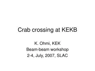
KEKB instrumentation and tuning for crab cavity tuning. Y. Funakoshi KEK. Evidence of crabbing motion (1): Streak camera. HER crabbing angle measurement and calculation. calculation @ streak camera. Tilt angle [rad]. calculation @ IP. HER crab phase. Crab OFF.

E N D
KEKB instrumentation and tuning for crab cavity tuning Y. Funakoshi KEK
HER crabbing anglemeasurement and calculation calculation @ streak camera Tilt angle [rad] calculation @ IP HER crab phase
Crab OFF Crab ON ( Vc = 1.31/0.92 MV) Evidence of crabbing (2): Beam-beam deflection x L/H=18/24 nm Bunch Current: 0.73/0.42 mA Bunch Current: 0.64/0.47 mA Σx_x’=11=230 +/- 3 m (OFF) Σx_x’=00=167 +/- 3 m (ON) Ratio ofSlope: Horizontaleffective size at IP reduces to 72% by the crab. • HER current was lost from 15 to 13.5 mA during scan. T. Ieiri
<COD> Beam-Position Change measured at a detector Method of measurement of beam-beam kick Beam-beam Kick (Rigid Gaussian) Δx: Horizontal Offset <Dynamic Beta> Effective Horizontal Size at IP By Fukuma & Funakoshi Missing partner method: Orbit difference of collision and non-collision bunches T. Ieiri
Calculation of Beam-Beam Kick with and without Crossing Angle Use code “BBWS” by Ohmi How to calculate the kick with an angle of 22 mrad x=24 nm x z <Slope in Linear Region> A particle is horizontally moved and the kick data are summed up, including the longitudinal profile. Head-on Result: • The measurement is consistent with the calculation. Crossing T. Ieiri
Effect of Transient Beam Loading Bunch train Gap : length of bunch train : Gap length T0 Revolution period Phase t D. Boussard T. Ieiri
HER / 800mA LER / 1530mA Phase and orbit shift along train with 3.06 spacing: Crab ON Z X ~0.2sx N=1585 T. Ieiri
HER/1260mA LER/1640mA Z Phase and orbit shift along train with 3.06 spacing: Crab OFF X N=1585 T. Ieiri
Measurements or experiences on impedance related issues • The following measurements were done before and after the installation of crab cavities (by T. Ieiri). • Bunch current dependence of coherent tune shift • Loss factor • Bunch lengthening as function of the bunch current • No significant difference was observed on these measurements between before and after crab. • We once observed a coupled bunch instability due to the crabbing mode. However, this was due to wrong setting of the detuning frequency. • As for the HOMs or LOMs, we have no experience that they induced any coupled bunch instability.
Crab system Adjustment • Crabbing voltage • Calibrated from klystron output power and the loaded Q value. • The measurement to adjust the phase using beam (below) also gives an independent calibration of the voltage. • Both are in good agreement within a few percent. • Crabbing phase • The reference phase is searched to minimize the beam orbit difference between the crabbing on and off, so that the bunch center is not kicked by the crabbing voltage. • In the high-current operation,the phase is shifted by 10 degrees from the reference phase to cure the oscillation observed at high-current crab collision (see yesterday’s talk). • Field center in the cavity • Searched by measuring the amplitude of the crabbing mode excited by a beam when the cavity was detuned. A local bump orbit was set to adjust the beam orbit on the cavity axis. K. Akai
H. Koiso, A. Morita 72 108 36 144 360 0 180 324 216 288 252 Crab Phase Scan (LER) Horizontal orbit by crab kick crab crab Horizontal kick by crab cavity (rad) (Estimated from orbits around the ring) Phase 0:174.8 deg. Vcrab set:1.0MV, estimated: 0.987MV agree very well
Crab phase vs Horizontal beam-beam kick • Balance of crab kick strength between HER and LER can be tested by measuring the horizontal offset with the same amount of the crab phase shifts. • Crab phase of LER and HER were changed by10°: The horizontal offset at IP (beam-beam kick) changed by15μm. (1)。(ideally zero) • Change LER phase only by1° or HER only by1° brought offsets of 16~19μm.(2)。(calculated value from crabbing angle is18μm.) • When we changed HER crab Vc from 1.55 to 1.43MV, the horizontal offset did not change with the same 10° phase change.(3)。 (1) (2) (3) 0.94MV (LER) 1.55MV (HER) 0.94MV (LER) 1.43MV (HER)
Orbit control and feedback near crab cavities • We have chosen QL=1~2 x10⁵ for a good compromise. • This value is suitable for operating the system with a possible error of ΔX=1mm, and • A high power source of 200 kW is sufficient for conditioning the cavity up to 2 MV. Dependence of RF power on the loaded Q value and a horizontal beam orbit for a beam current of 2 A. Typical parameters for the crab crossing. • ★Orbit feedback around crab cavities • Only horizontal orbit feedback is considered. • 4 horizontal steering magnets to make an offset bump for each ring • 4BPM to monitor the offset at the crab cavity. 2 upstream (entrance) BPMs and 2 downstream (exit) System speed (design) <~1 Hz. • We found that the orbit is stable enough.Usually, we do not need the orbit feedback.
LER crab phase ± 1 deg HER crab phase Phase stability • Spectrum of pick up signal is consistent with phase detector data. • Phase fluctuation faster than 1 kHz is less than ± 0.01°, and slow fluctuation from ten to several hundreds of hertz is about ± 0.1°. • They are much less than the allowed phase error obtained from the beam-beam simulations for the crabbing beams in KEKB. According to b-b simulation by Ohmi-san, allowed phase error for N-turn correlation is 0.1×√N (degree). Span 500 Hz Sideband peaks at 32, 37, 46, 50, 100 Hz. Span 10 kHz Span 200 kHz Sideband peaks at 32kHz and 64kHz. Phase detector signal. Beam current was 385mA (HER) and 600 mA (LER). Spectrum around the crabbing mode measured at a pick up port of the LER crab cavity. Beam current was between 450 and 600 mA. K. Akai
Horizontal offset scan • The (HER) beam current seems to be limited by the short life time of the LER beam. LER lifetime Collision center given by the beam-beam kick • The (LER) beam lifetime is very asymmetric with respect to H offset.
Beta’s with dynamic beam-beam effect crab before summer βx*= 0.9m with/without beam-beam effects crab this fall βx*= 0.9m
Aperture survey around HER crab • Scan of HER Crab Alignment Bump • Original bump height: ~-6.5 mm necessary to minimize the beam loading • Higher bumps made the lifetime longer (peak at a bump with Δx = ~ -4mm). • Mis-alignment of HER crab cavity? • After the machine was shutdown, we actually found a mis-alignment of the HER crab cavity which is consistent with the original bump height. • Necessity of the additional 4mm bump is still a mystery. I+ x I- ~1.5mA2 Alignment Bump Crab Cavity ~ 4mm original height Life peak 10
Horizontal offset target scan I+ x I- ~1.5mA2 Original crab bump Could not go to the right direction. crab bump -5mm in addition to original crab bump Physical aperture around the crab is responsible to the short beam lifetime and restricted the luminosity. 11
Summary • The crabbing motion of the beam with a single crab cavity scheme has been confirmed by the streak camera measurement. • Effective head-on collision was confirmed by the measurement of the beam-beam deflection. • The synchronous phase shifts along the train from the transient beam loading have some size at KEKB. However, their impact on the luminosity is very small owing to the cancelation of the effect between the two rings. • We have observed almost no harmful effects due to the crab cavities or the single crab cavity scheme (global crab cavity scheme) from the viewpoint of the beam dynamics. • Dynamic aperture, synchro-betatron resonance (yesterday’s talk) • Bunch current dependent tune shift, loss parameter, bunch lengthening, coupled bunch instabiity
Summary [cont’d] • Crab Vc is determined so as to maximize the luminosity in the real beam tuning situation at KEKB. • The phase errors of the crab cavities are much less than the allowed level of the errors obtained from the beam-beam simulations. • At KEKB, the dynamic beam-beam effects (emittance enlargement and the beta-beating) are very important, since the horizontal tune is very close to the half-integer. Due to this problem, physical aperture around the crab cavity limited the ring acceptance. After solving this problem, we could increase the bunch current (of HER) and the luminosity. • In autumn this year, we will operate KEKB for about 2 months. There is possibility that it will be the final opportunity to operate the crab cavities at KEKB.