Download
1 / 22
220 likes | 354 Vues
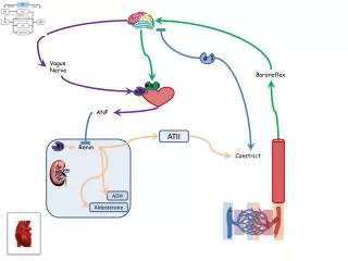
The M2 ASIC. A mixed analogue/digital ASIC for acquisition and control in data handling systems. Olle Martinsson. AMICSA, October 2-3, 2006. M2 summary. A mixed analogue/digital ASIC, including 32 kgates and a 12 bit ADC, developed by Austrian Aerospace and Saab Space under an ESA contract

E N D
The M2 ASIC A mixed analogue/digital ASIC for acquisition and control in data handling systems Olle Martinsson AMICSA, October 2-3, 2006 SAAB SPACE
M2 summary • A mixed analogue/digital ASIC, including 32 kgates and a 12 bit ADC, developed by Austrian Aerospace and Saab Space under an ESA contract • Main application as generic core circuit for data handling I/O board • Controlled via OBDH bus or UART interface • Digital I/O functions include all common data handling system interfaces, such as: • High level command pulse generation • Serial command and acquisition • Etc. • 3.3V supply • Low power, typical consumption 12mW SAAB SPACE
M2 block diagram Configuration Digital I/O user interface Control interface Address strap Reset Analog I/O interfaces SAAB SPACE
M2 implementation • Commercial, epi-layered CMOS technology, AMIS 0.35µ with analog options (double poly capacitors, high resistive poly resistors) • Radiation tolerant by “Rad hard by design” • Digital cell library developed within the project • Digital part designed using VHDL, logic synthesis and place & route • Chip size 25mm2 • Prototypes via Europractice MPW in 160 pin CQFP package • Tested showing full functionality and full performance at first run • Implemented on a prototype I/O board for system level test, showing similar or better performance compared to existing designs SAAB SPACE
Rad hard by design The methodology to reach radiation hardness has basically been the same for analogue and digital parts. This includes: • Selection of submicron CMOS assures small threshold voltage drifts • NMOS edge leakage avoided by enclosed shaped transistors • Leakage between NMOS devices avoided by guard rings • Latchup avoided by guard rings and good substrate connections • SEU hardness achieved by means of resistive feedback in flip-flops • Limits maximum possible clock rate, but • Makes the design hard also to transients in combinatorial logic Only low level measures, mainly on layout level, to achieve radiation hardness radiation aspects have only marginal impact on system, VHDL and schematic level design SAAB SPACE
Cell library design based on “shadow” library M2 cells selected as a subset of and compared with cells of a commercially available “shadow” library of a similar process Cell library, just like analog parts and top level design, developed using a low cost PC based tool from Tanner, including: • Schematic editor • Spice simulator • Layout editor • Design rule check • Extraction • Layout vs. schematic • Place & route SAAB SPACE
Digital cell library • Library consists of: • 3 flip-flops • 14 combinatorial core cells • 4 digital I/O cells • 4 power I/O cells • Size of NAN2 gate 8.4 x 21 μm2, indicating 5.7 kgates/mm2 • Size of NAN2 in AMIS library for the same technology, MTC45000: 4.5 x 12 μm2, indicating an area penalty factor 3.3 for the radiation hardness • Gate density of the M2 after place & route = 31.7kgates / 15.7mm2 = 2.0 kgates/mm2 (only 3 metal layers used for place & route, limitation by Tanner tools) SAAB SPACE
Cell layout examples MUX2 Output pad cell with tristate SAAB SPACE
Digital design flow using the “shadow” library • Digital part designed using a standard flow including VHDL and digital simulation • Logic synthesis performed using the similar “shadow” library, but limited to use only these cells that have been implemented in the M2 library • Gate level simulation can be performed using the shadow library • Backannotation (timing feedback from layout) not possible, good timing margins needed • Layout routing verified using netlist from digital design, extraction of layout and LVS SAAB SPACE
Analogue part description • ADC third order MASH ΣΔ type, 12.28 bits (4960 codes) • External 1.25V reference • Time discrete, switched capacitor based, operating at 500kHz (typical) • One conversion within minimum 100µs, including time for multiplexer settling • Buffered signal and reference inputs • 66 channel input multiplexer • Digital outputs for control of external multiplexer • Switchable thermistor conditioning (for resistance measurements), giving: • Compact design (one conditioning resistor common for many channels) • High precision (minimum number of error sources) • Low power, only one channel powered at a time • Direct thermistor interface, no additional front-end needed • Includes comparator for binary acquisition of analog inputs (digital bilevel and digital relay) SAAB SPACE
Digital noise Digital noise, which is a potential problem, especially substrate coupled, was handled by: • Differential design • Topology (sigma-delta) • Separated digital and analogue supply lines • Input filter (especially considering unbalanced, non-differential inputs) • Early clock to analogue functions • Careful design of signal interfaces between digital to analogue domains, e.g. filters are added where feasible • Careful package grounding, considering that grounds anyway are connected via excessive substrate connections SAAB SPACE
M2 layout 4921.5µ x 5028.5µ ≈ 24.75 mm2 SAAB SPACE
Test result summary • Power consumption typically 12mW, approximately 50/50 analogue/digital • Functional test OK • Analog performance: • ADC linearity measured to DNL < 0.17LSB and INL < 0.17LSB (1 sample) • Gain error: -0.8LSB average, 0.6LSB standard deviation (18 samples) • Offset error: -0.16LSB average, 0.14LSB standard deviation (18 samples) • Environment tested: • Supply voltage 2.8 to 3.6V • Temperature -30 to +85C • Total dose radiation up to 300krad and annealing • Heavy ion test up to 106MeV/mgcm2 effective LET • Life test, 1000 hours in +125C • ESD test up to 4kV HBM • Virtually radiation immune, both concerning total dose and heavy ions • No ESD damage up to 4kV HBM • Good stability considering: • Input common mode variations • Supply voltage variations • Temperature variations • Ageing • 17 of 18 tested samples showed full function and performance (yield = 94%) SAAB SPACE
Measured ADC linearity performance DNL = Differential non-linearity INL = Integrated non-linearity Vertical scale in LSB SAAB SPACE
Measured ADC performance vs. temperature GE = Gain Error OE = Offset Error 1 LSB = 0.5 mV SAAB SPACE
Measured ADC performance vs. supply voltage GE = Gain Error OE = Offset Error 1 LSB = 0.5 mV SAAB SPACE
Measured ADC performance vs. life in 125C 1 LSB = 0.5 mV SAAB SPACE
Measured ADC performance vs. total dose 1 LSB = 0.5 mV SAAB SPACE
Measured supply current vs. total dose IDDA = Analogue core supply IDDI = Digital core supply Note, step in IDDI was due to a change in test setup (affected also the reference M2) SAAB SPACE
M2 SEE test summary Conclusion: The M2 is considered immune to heavy ions regarding SEL and register SEU Note: Maximum recorded acquisition error at LET=106 was 0.34% of full scale SAAB SPACE
via1 array 3D cell SAAB SPACE
www.space.se SAAB SPACE