Download
1 / 5
50 likes | 75 Vues
MEMORY ORGANIZATION. Memory Hierarchy Main Memory Auxiliary Memory Associative Memory Cache Memory Virtual Memory Memory Management Hardware. Memory Hierarchy. MEMORY HIERARCHY. Memory Hierarchy is to obtain the highest possible

E N D
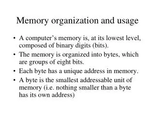
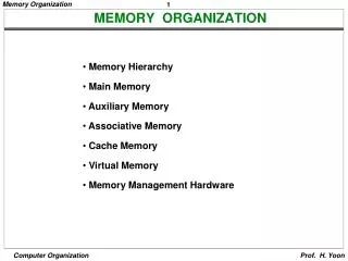
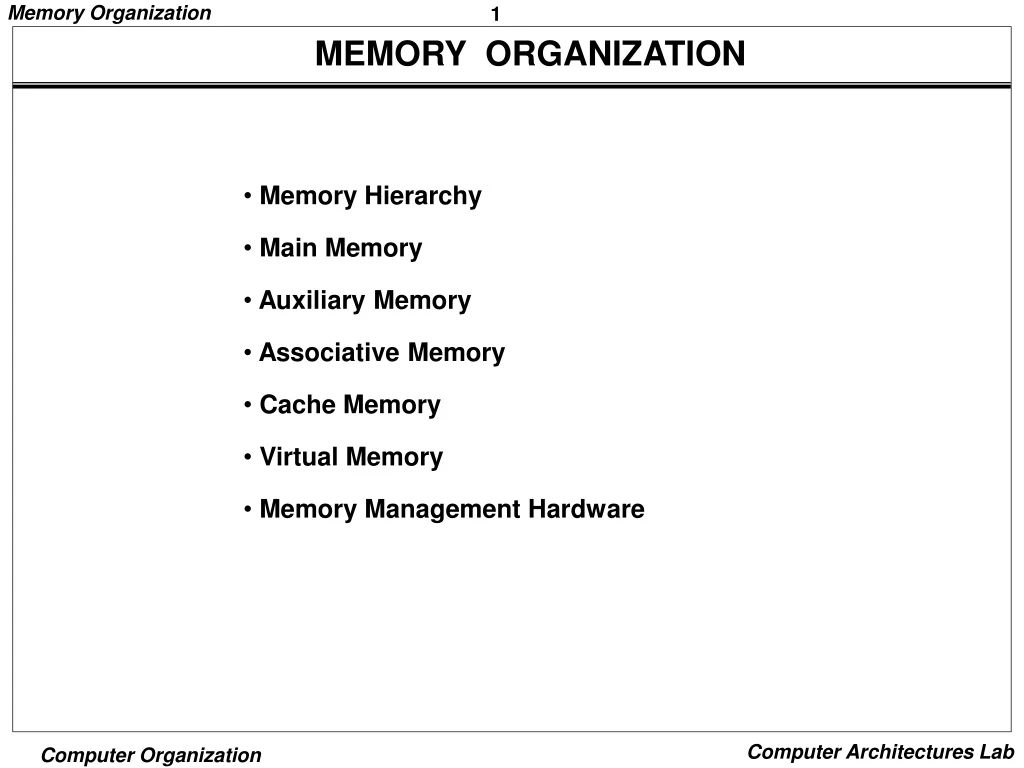
MEMORY ORGANIZATION • Memory Hierarchy • Main Memory • Auxiliary Memory • Associative Memory • Cache Memory • Virtual Memory • Memory Management Hardware
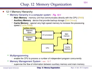
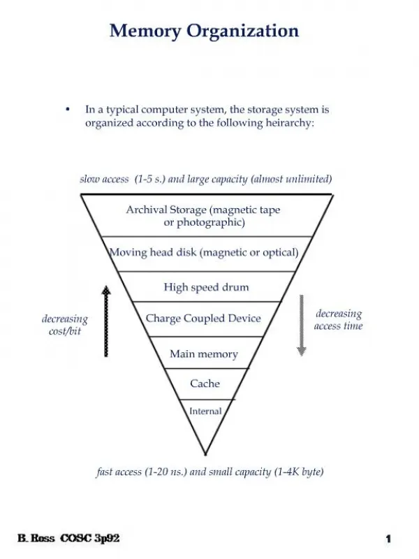
Memory Hierarchy MEMORY HIERARCHY Memory Hierarchy is to obtain the highest possible access speed while minimizing the total cost of the memory system Auxiliary memory Magnetic I/O Main tapes memory processor Magnetic disks Cache CPU memory Register Cache Main Memory Magnetic Disk Magnetic Tape
Main Memory MAIN MEMORY RAM and ROM Chips Typical RAM chip Chip select 1 CS1 Chip select 2 CS2 128 x 8 Read RD 8-bit data bus RAM Write WR 7-bit address AD 7 Memory function State of data bus CS1 CS2 RD WR Inhibit High-impedence 0 0 x x Inhibit High-impedence 0 1 x x Inhibit High-impedence 1 0 0 0 Write Input data to RAM 1 0 0 1 Output data from RAM Read 1 0 1 x Inhibit High-impedence 1 1 x x Typical ROM chip CS1 Chip select 1 CS2 Chip select 2 512 x 8 8-bit data bus ROM 9-bit address AD 9
Main Memory Address bus Hexa address Component 10 9 8 7 6 5 4 3 2 1 RAM 1 RAM 2 RAM 3 RAM 4 ROM 0000 - 007F 0080 - 00FF 0100 - 017F 0180 - 01FF 0200 - 03FF 0 0 0 x x x x x x x 0 0 1 x x x x x x x 0 1 0 x x x x x x x 0 1 1 x x x x x x x 1 x x x x x x x x x Memory Connection to CPU - RAM and ROM chips are connected to a CPU through the data and address buses - The low-order lines in the address bus select the byte within the chips and other lines in the address bus select a particular chip through its chip select inputs MEMORY ADDRESS MAP Address space assignment to each memory chip Example: 512 bytes RAM and 512 bytes ROM
Main Memory CONNECTION OF MEMORY TO CPU CPU Address bus 16-11 10 9 8 7-1 RD WR Data bus Decoder 3 2 1 0 CS1 CS2 128 x 8 Data RD RAM 1 WR AD7 CS1 CS2 128 x 8 Data RD RAM 2 WR AD7 CS1 CS2 128 x 8 Data RD RAM 3 WR AD7 CS1 CS2 128 x 8 Data RD RAM 4 WR AD7 CS1 CS2 1- 7 512 x 8 Data 8 ROM AD9 9


![[Packet] My Memory Organization](https://cdn1.slideserve.com/1905829/packet-my-memory-organization-dt.jpg)