Download
1 / 28
310 likes | 531 Vues
CAFS On-Line Orientation Montgomery County Fire & Rescue Service. CAFS Components. Other CAFS System Design Details. Module Objectives Learn and understand Compressor operating characteristics Learn and understand CAFS associated equipment operation & warnings

E N D
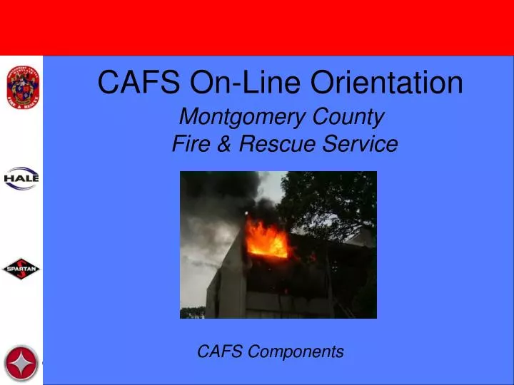
CAFS On-Line Orientation Montgomery County Fire & Rescue Service CAFS Components
Other CAFS System Design Details Module Objectives • Learn and understand Compressor operating characteristics • Learn and understand CAFS associated equipment operation & warnings • Learn and understand Manifold piping and flow characteristics MCFRTA 2008
Compressor and System Details • Air Compressor • TPM • Direct Tank Fill • Auto Fill • Tank to Pump Valve • TRV-120L • Manifold Piping • EZ-Fill MCFRTA 2008
Positive Displacement vs Non-Positive Displacement Pumps • Rotary-Screw Air Compressor • Positive Displacement • Needs Shaft Speed to produce volume and pressure • Impeller Driven Water Pump • Non-Positive Displacement • In cases where there is incoming pressure, pump may be turning at idle speeds MCFRTA 2008
Speed Comparison The compressor is run off a belt from the pump gear box. Therefore the impeller must be turning at above 1000 rpm to provide sufficient power for the compressor. How do you maintain Engine RPMs for compressor output when operating from a pressurized water source? MCFRTA 2008
The Answer! • Total Pressure Master Relief Valve System or • Direct Tank Fill mechanism plumbed off an intake - Autofill Valve MCFRTA 2008
Total Pressure Master • In situations where you have an intake fed by a pressurized water source, you can utilize the TPM to maintain pump pressure while increasing engine RPMs to ensure adequate volume from the air compressor. MCFRTA 2008
Direct Tank Fill • Avoid intake pressure by using and refilling booster tank. • Autofill Valve is plumbed off rear intake, outboard of rear MIV. • Requires 10 psi of incoming pressure to operate. MCFRTA 2008
Direct Tank Fill • Requires 10 psi of incoming pressure to operate. • If there is insufficient pressure, valve will not operate in Auto mode. You will know this because the blue light will not be on. • Will operate in manual mode at lower than 10 psi but you need to monitor supply pressure. MCFRTA 2008
AutoFill System • In Auto mode the booster tank level is monitored. When the booster tank falls below 3/4, the valve opens. When the tank refills to 7/8 the valve shuts. In Manual Mode the operator can open and close the valve by utilizing the toggle switch. MCFRTA 2008
Air Operated Tank to Pump Override New engines are equipped with an air operated tank to pump valve. The valve automatically opens when the pump goes into gear. If the valve fails, it will fail in the open position. If the operator wishes to close this valve, just push the close button. MCFRTA 2008
Why automatically open the tank to pump valve? • It is preferential to run the CAFS system off tank water so as to provide proper power to air compressor. • The pump also provides cooling water for the gear box and the air compressor. It is essential that the pump is never run without water in it. • Removes a pump operator step. You must remember to close this valve if you choose to perform plain water pumping from a pressurized or draft source. MCFRTA 2008
Water Path for CAFS Rear Connection Autofill valve (operating) Tank to Pump (open) Booster Tank Pump Supply hose Rear MIV (closed) MCFRTA 2008
Use the Rear Intake for CAFS MCFRTA 2008
Rear Piping Autofill over-ride Autofill piping Main rear intake piping Rear drain Rear MIV relief valve MCFRTA 2008
Water Path for Plain Water Rear Connection Autofill valve (not operating) Tank to Pump (closed) Booster Tank Pump Supply Hose Rear MIV (open) MCFRTA 2008
CAFS vs. Plain Water MCFRTA 2008
Operator cautions • When in CAFS mode you should always use the rear intake. • Be aware that when obtaining your supply through the Autofill valve and booster tank, there will be no positive pressure indication on your intake gauge. • You will have to ensure that your supply line stays charged, as there will be no immediate indication of any supply problems. If you are not watching the supply line, your first indication of an issue will likely be when the Autofill valve fails to operate and you notice that the Autofill valve blue light is out. MCFRTA 2008
Review What automatically happens when pump is put into gear? • Tank to Pump valve opens • Foam system powers on and is ready • Air compressor powers on and is ready MCFRTA 2008
Simple CAFS Operations Step by Step • Put Engine in Pump Gear. Pump is ready for CAFS. • Connect Supply Line to Rear intake. Do NOT open Rear MIV. • Stretch handline, ensure bed is clear. • Use throttle to increase discharge pressure to desired point for flow. Open discharge valve slowly. • Monitor gauges. • Before putting away handline, turn foam pump and air compressor off. Flow plain water through line until stream runs clear. MCFRTA 2008
Plain Water Operations Step by Step • Put Engine in Pump Gear. Pump is ready for CAFS. • Turn off Foam Pump and Air Compressor. Pump is now in Plain Water mode. • Connect Supply Line to desired intake. • Open MIV to desired intake. • Stretch handline, ensure bed is clear. • Use throttle to increase discharge pressure to desired point for flow. Open discharge valve slowly. • Monitor gauges. • Put away hose. MCFRTA 2008
CAFS Manifold CAFS Manifold is equipped with gate valve which regulates water flow. If a “Dryer” foam is selected than the valve partially closes. This allows less water into the manifold but allows more air into the stream. This valve is controlled by the CAFS Controller. When switching from Wet to Fluid Foam, or Fluid to Dry Foam, you must hold the up arrow down for three beeps before the controller will allow this action. This delay is to make sure that the operator really wishes to perform this action. MCFRTA 2008
CAFS Manifold Settings • 3 Gated Settings - adjusted by using wet / dry arrows (must hold down for three beeps) • Full Flow (Wet) • Medium Flow (Fluid) • Reduced Flow (Dry) • Values • 1000 GPM (wet) • 400 GPM (fluid) • 40 GPM (dry) MCFRTA 2008
WARNING! • Always use Wet (default setting) CAFS for interior fire attack. • Never switch to fluid or dry CAFS when any crews are operating in a fire attack mode! Switching to drier foam settings will decrease the amount of water available to the crews inside! MCFRTA 2008
CAFS Audible Alarm sounds • When the air compressor oil temperature exceeds 205。F (96。C) • When the foam concentrate is running low • If you don’t refill the Class A foam tank the compressed air foam operation will end. • The compressor drive clutch is disengaged and the compressor is powered off. • The foam system shuts off. MCFRTA 2008
EZ-Fill System • Automatic Foam Reservoir Refill • For Class A tank ONLY!!! • Industrial type Cam-lock coupling hooks to pick up tube for insertion into foam bucket. MCFRTA 2008
EZ Fill System • 5 gpm pump • Push Fill. Shuts off automatically after 60 seconds or when it senses foam cell is full. • Good idea to flush pickup tube after use. You can also flush EZ fill pump if desired. • Tank selection switch on right is NOT hooked up on our pumpers. Again, this system is only for use with the Class A foam tank ONLY. Class B foam will be refilled from top of pumper directly into Class B tank. MCFRTA 2008
Review Questions • Why is it necessary to route water through the rear intake for CAFS operations? • Should the rear MIV be open or closed when using CAFS? Why? • List what happens when the pump is engaged? • What happens when the Class A foam tank is getting close to running out? What will happen if you let the tank run dry? • Can you use the EZ Fill System to fill the Class B Foam tank? MCFRTA 2008