Download
1 / 31
310 likes | 382 Vues
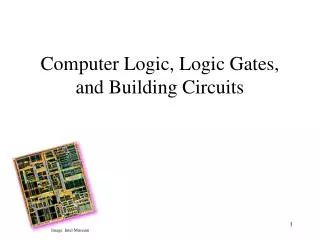
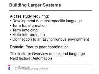
Building Larger Circuits. Today: First Hour : Combinational Building Blocks Section 4.1 of Katz’s Textbook In-class Activity #1 Second Hour : Tri-state and Open Collector Gates, ROMs. Section 4.2 of Katz’s Textbook In-class Activity #2.

E N D
Building Larger Circuits • Today: • First Hour: Combinational Building Blocks • Section 4.1 of Katz’s Textbook • In-class Activity #1 • Second Hour: Tri-state and Open Collector Gates, ROMs. • Section 4.2 of Katz’s Textbook • In-class Activity #2
To simplify large Boolean functions, we use logic minimization software (espresso) We can use multi-level minimization when speed is not a problem. Use Programmable Logic Arrays to implement large circuits in an automated manner. Recap: Today: We’ll learn about another tool for building large circuits: higher-level building blocks (modules).
A0 A1 B0 B1 Sa Sb MUX MUX B A Sum Ss DEMUX S0 S1 Building Blocks • The Idea: • Assemble your system using generic “building blocks.” • Examples: • PLA • Adder, • Multiplexor, • De-multiplexor, • Decoder, • Encoder
Terminology I0 and I1 are input lines Z is the output line A is the control signal I 0 2:1 Z MUX I 1 A Z 0 I0 1 I1 A A 2:1 Multiplexor • Truth Table Boolean Function: Z = A' I0 + A I1
I1 I0 A Z 0 000 0 0 10 0 101 0 1 10 1 000 1 0 11 1 101 1 1 11 A Z 0 I0 1 I1 Expanded Truth Table
I 0 2:1 Z MUX I 1 I 0 I 1 I A 2 I 3 8:1 Z I MUX 4 I I 5 0 I I 6 1 4:1 I I Z MUX 7 2 I 3 A B C A B Larger MUXes
I 0 8:1 0 4:1 I 1 MUX MUX 1 I 2 2 3 I S S 2:1 3 1 0 MUX I 0 4 4:1 I 1 MUX 5 I 2 6 I 3 S S 7 1 0 Cascading MUXes Z 0 1 S A B C
2n-1 :1 multiplexor can implement any Boolean function of n variables needs n-1 control variables; the remaining variable is used as a data input to the multiplexor Example: F(A,B,C) = m0 + m2 + m6 + m7 = A' B' C' + A' B C' + A B C' + A B C = A' B' (C') + A' B (C') + A B' (0) + A B (1) Implementing Logic with MUX
C C C 0 F 0 C 1 4:1 0 2 MUX 1 3 1 S1 S0 A B Example 1 0 0 1 1 2 A B C F F 8:1 0 3 MUX 0 0 0 0 1 4 0 5 0 0 1 0 1 6 1 7 S2 S1 S0 0 1 0 1 A B C 0 1 1 0 1 0 0 0 1 0 1 0 1 1 0 1 1 1 1 1
Decoder: single data input, n control inputs, 2n outputs control inputs (called selectsS) represent binary index of output to which the input is connected data input usually called "enable" (G) Usually Enable = G = 1 De-multiplexors (DMUX) Opposite of MUX, also called Decoders
2:4 DMUX Enable Output0 Output1 Output2 Output3 Select1 Select0
0 A B C 1 A B C 2 A B C 3 A B C 4 A B C 5 A B C 6 A B C 7 S S S A B C 2 1 0 DMUX as a Logic Block Enable 3:8 DMUX (decoder) A B C
F1 = A B C D + A B C D + A B C D F2 = A B C D + A B C F3 = (A + B + C + D) Example Implement the following 4-input, 3-output Boolean function using a decoder (DMUX):
0 A B C D 1 A B C D F 1 2 A B C D 3 A B C D 4 A B C D 5 A B C D 6 A B C D 4:16 7 A B C D decoder 8 A B C D F 2 9 A B C D 10 A B C D 1 1 A B C D 12 A B C D 13 A B C D 14 A B C D F 3 15 S S S S A B C D 3 2 1 0 Enb = 1 A B C D
Do Activity #1 Now Get to know MUX and DMUX building blocks
New Kinds of Gates, “wired logic”: 3-state output gates Open-collector gates Build a MUX easily with these new gates. Read-only Memory (ROM) New Kinds of Gates, Read-only Memory
OE 0 1 1 A X 0 1 A B Equivalent Circuit OE A B OE 3-State Gates “output enable” Truth Table Three possible outputs: 0, 1, or Z Z means output disconnected Z does not reduce to 1 or 0 B Z 1 0
What’s the Big Idea? Allows the output of more than one gate to be connected to the same wire - “wired logic” Especially useful for allowing building blocks to exchange data over shared wires - buses Works only as long as only one gate has its output enabled at the same time Bus Device 3 Device 1 Device 2
Input0 F OE Input1 OE InputSelect Multiplexer using 3-State Logic Non-inverting Buffers When InputSelect = 1, Input1 is connected to F When InputSelect = 0, Input0 is connected to F This is a 2:1 Mux 3-state Buffer
I.C. I.C. Open Collector Gates Another way to connect multiple gates to the same output wire The output of an open collector gate is like a switch connected to ground output for logic “1”output for logic “0” Note: If you put a logic probe on an unconnected open-collector pin, it will indicate a logic0 ornothing.
+5V I.C. Pull-up Resistors +5V I.C. Y = 0 Y = 1 Resistors: 1 - 10 k typical
Two Gates and a Resistor +5V Y Y becomes 0 when any one switch is closed
+5V A Output B C D Wired Logic Special symbol on OC gates: output bar If A and B are 1, Output is actively pulled low If C and D are 1, Output is actively pulled low If one gate is low and the other high, then low wins If both gates are 1, the Output floats. Pull it high with a resistor
+5V A Output B C D So What’s the Big Idea?? Wired Logic !! What is Output(A,B,C,D)? Click for answer Output = (A B + C D)' = (A B)' (C D)' = (A' + B')(C' +D') = A' C' + A' D' + B' C' +B' D' If A and B are 1, Output is actively pulled low If C and D are 1, Output is actively pulled low If one gate is low and the other high, then low wins If both gates are 1, the Output is pulled up to logic 1.
+5V R X I.C. Another Practical Issue Useful for lighting Light Emitting Diodes (LEDs) What happens to the LED when X = 1? When X = 0? Click for the answer No current = OFF Current = ON
m output n address lines lines Memory Array n Decoder n 2 words by 2 word m bits lines Read-Only Memories Sort of like a PLA structure with a fully decoded AND array!
Store data in a non-volatile manner Like PLA’s, you can buy programmable ROMs (PROMs) Implement combinational functions Applications of ROMs
ROM vs. PLA combinational functions • ROM advantageous when • design time is short (no need to minimize output functions) • most input combinations are needed (e.g., code converters) • little sharing of product terms among output functions • Downside: • size doubles for each additional input • can't use don't cares • PLA advantageous when • design tool like espresso is available • there are relatively few unique minterm combinations • many shared minterms among the output functions • Downside: constrained fan-ins on OR arrays
2764 VPP PGM PGM A12 A12 A11 A11 A10 A10 O7 O7 ADDRESS LINES A9 A9 O6 O6 A8 A8 O5 O5 DATA LINES (tri-state) A7 A7 O4 O4 A6 A6 O3 O3 A5 A5 O2 O2 A4 A4 O1 O1 A3 A3 O0 O0 A2 A2 A1 A1 A0 A0 CS CS OE OE CHIP SELECT OUTPUT ENABLE ROM Example • Questions: • How many words? • How many bits in each word? • How many bits overall? • Click for answer 213 = 8K = 8 192 8 216 = 64K = 65 536
Choices, choices ... You can implement logic functions many ways: Discrete gates AND/OR NAND/NAND PLAs or PALs Muxes Demuxes (decoders) ROMs Existence of alternatives no clear winner
Due: End of Class Today RETAIN THE LAST PAGE (#3)!! For Next Class: Bring Randy Katz Textbook, & TTL Data Book Required Reading: Sec 5.1 of Katz This reading is necessary for getting points in the Studio Activity! Do Activity #2 Now