Download
1 / 17
170 likes | 329 Vues
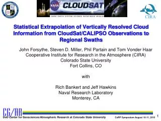
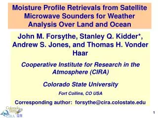
Donald L. Reinke, John M. Forsythe and Thomas H. Vonder Haar CIRA Colorado State Univ. Fort Collins CO. Probability of Cloud-Free Line of Sight (PCFLOS) derived from CloudSat Cloud Profiling Radar (CPR) and coincident CALIPSO lidar data. CFLOS “Problem”.

E N D
Donald L. Reinke, John M. Forsythe and Thomas H. Vonder Haar • CIRA • Colorado State Univ. • Fort Collins CO Probability of Cloud-Free Line of Sight (PCFLOS) derived from CloudSat Cloud Profiling Radar (CPR) and coincident CALIPSO lidar data
CFLOS “Problem” The Problem: CFLOS, beneath an opaque cloud layer , has been impossible to determine, directly, from passive space sensors Corollary: Passive satellites measure cloud tops well … and surface observers the bases … but neither do an adequate job of characterizing the intervening layers … View from passive vis/ir sensor No information about CFLOS here … PCFLOS from CloudSat and CALIPSO
A B Addressing the Problem – Cloud Profiling Radar TOA CloudSat Radar Reflectivity Passive vis/ir sensors likely see this cloud top as a homogenous opaque layer Sfc Here an opaque cloud at “B” hides the fact that there is a poor CFLOS at levels below the cloud top, while at “A” it hides a significantly better CFLOS just below the upper cloud layer. PCFLOS from CloudSat and CALIPSO
C l o u d S a t:94 GHz Cloud-Profiling Radar Near circular, sun-sychronous orbit … ~705km altitude, 14.5 orbits/day, 16-day revisit cycle PCFLOS from CloudSat and CALIPSO
CloudSat:94 GHz Cloud-Profiling Radar • Wavelength ~ 3 mm • Near-nadir Pointing (0.16o forward) • Pulse Repetition Freq. ~ 4000 • Return signal processed every160 milliseconds (~ 6 times/sec) • at 4000 PRF … ~ 630 pulsesare averaged to produce a vertical cloud image (“profile”) • 160 msec = 1.07 km along ground track PCFLOS from CloudSat and CALIPSO
1 GRANULE= 1 orbit of data (~ 40,786 km / ~ 37,082 profiles) “Data Window” 30-km 1.3 km SATELLITE DIRECTION OF MOVEMENT 98.9 minutes per orbit 14.56 orbits/day Granules, Profiles and Bins :CPR footprint & granule size TOA Sfc Top of Data Window Each“Profile”has 125 vertical“BINS”(~30 km) Each verticalbinis 240 m thick Surface 1.7 km along-track PCFLOS from CloudSat and CALIPSO
CALIPSO:Dual-Channel Lidar • (CALIOP) “Cloud-Aerosol Lidar with Orthogonal Polarization” • 532 and 1062 nm wavelengths • Nadir Pointing • Vertical resolution 30m, 60m (< 8km) • 80m instantaneous footprint • Products generated at a horizontal resolution of 333m, 1km, and 5km CloudSat Footprint CALIPSO Footprint PCFLOS from CloudSat and CALIPSO
L20 O O O O CFLOS computed at 20 vertical levels O O O O O O O O O O O O O O L01 O CFLOS calculation Profiles 1 2 3 4 5 6 7 8 9 …………………………..…….. n For each CloudSat profile, CFLOS is determined by looking at 10o intervals from nadir to 90o (horizontal) at each of 20 vertical levels. These levels extend from .96-km to 19.2-km altitude at ~1-km intervals. (every 4 bins in the vertical = 4X240m = .96km) PCFLOS from CloudSat and CALIPSO
CFLOS Calculation Cloud-Free Line-of-Sight Distance (km) CFLOS is calculated by determining the distance (km) that we can see before encountering a cloud. “0” indicates that we did not have a cloud in the line-of-sight. Vertical Level View angle (from Nadir) PCFLOS from CloudSat and CALIPSO
PCFLOS from CloudSat CPR Probability of CFLOS from CloudSat CPR Location: L20 (TOA) View: Nadir January 2007-2010 Probability of CFLOS from CloudSat CPR Location: L20 (TOA) View: Nadir July 2006-2010 PCFLOS from CloudSat and CALIPSO
PCFLOS from CALIPSO Lidar Probability of CFLOS from CALIPSO Lidar Location: L20 (TOA) View: Nadir January 2007-2010 Probability of CFLOS from CALIPSO Lidar Location: L20 (TOA) View: Nadir July 2006-2010 PCFLOS from CloudSat and CALIPSO
Comparison With Typical Cloud Fraction Products Probability of CFLOS from CloudSat CPR Location: L20 (TOA) View: Nadir January MODIS Cloud Fraction (January 2007) PCFLOS from CloudSat and CALIPSO
CFLOS from CloudSat CPR … Varying Levels O O O L20 O O O L14
CFLOS from CloudSat CPR … Varying Levels 10-km altitude view: nadir Probability of CFLOS from CloudSat CPR January 2007-2010 5-km altitude view: nadir 2-km altitude view: nadir PCFLOS from CloudSat and CALIPSO
CFLOS from CloudSat CPR … Varying View Angle O L20 O L14
PCFLOS from CloudSat CPR … Varying View Angle 10-km altitude view: Nadir 10-km altitude view: 50o off nadir 10-km altitude view: 60o off nadir 10-km altitude view: 70o off nadir Probability of CFLOS from CloudSat CPR January 2007-2010 10-km altitude view: 80o off nadir PCFLOS from CloudSat and CALIPSO
Summary … • CloudSat CPR data provides and exciting new view of the vertical distribution of cloud • This 3-D view can be used to calculate CFLOS at varying vertical levels and view angles • CPR-derived CFLOS can be used to validate CFLOS derived by “apriori cloud thickness” methods … or for the initialization/verification of forecast model output of CFLOS • PCFLOS Viewer PCFLOS from CloudSat and CALIPSO