Download
1 / 21
240 likes | 585 Vues
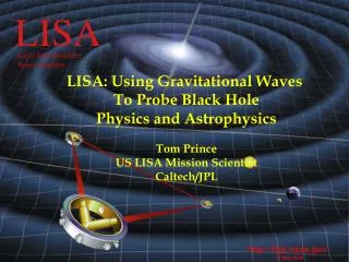
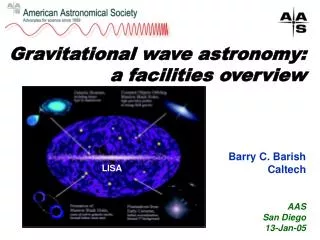
LISA Autocollimator. Jenna Walrath 8/19/09. Laser Interferometer Space Antenna (LISA). Mission Will detect gravitational waves within a frequency range from 0.03 mHz to above 0.1 Hz Structure Three spacecraft in equilateral triangle with 5 million km sides.

E N D
LISA Autocollimator Jenna Walrath 8/19/09
Laser Interferometer Space Antenna (LISA) • Mission • Will detect gravitational waves within a frequency range from 0.03 mHz to above 0.1 Hz • Structure • Three spacecraft in equilateral triangle with 5 million km sides
Laser Interferometer Space Antenna (LISA) http://www.nasa.gov/centers/goddard/images/content/181573main_lisa_LO.jpg
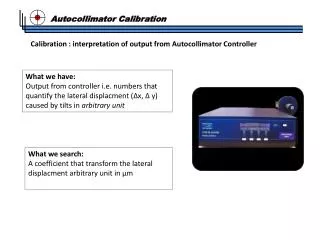
What is an autocollimator? • Optical device for measuring angles • Basic idea is to image something on a camera and measure the deflections of the image Laser Beam splitter CCD or other readout device Lens Mirror
Specifications • Dynamic range of 1° • Noise level of 1nrad/√Hz • Work at a distance of 1m
Initial Design Goal • Instead of point source of light, use a grating • Instead of imaging just one grating, image three—two stationary reference patterns and one dynamic pattern
The Plan LED w/ diffuser Top View Grating CCD Camera Mirror Beamsplitter Lens Two Beamsplitters
Humble Beginnings Side View (sort of) Paper Diffuser Grating Red LED Lens w/ aperture CCD Camera Mirror
Humble Beginnings 6/23/09 High-tech light-shielding device Mirror Light with diffuser and grating Lens with aperture Camera
Improvements to the Plan • double black line in the grating • converging lens between the LED and the grating • Allowed us to get rid of the diffuser • Switched from red (627nm) LED to green (530nm) LED • Encased the whole thing in Styrofoam • Instead of 3 images, just use 1 reference pattern and 1 dynamic pattern (so only one beamsplitter at the end rather than two)
Current Design Green LED light source Auxiliary lens 40R/60T Beamsplitter Grating w/ 135 μm slits Mirror CCD Camera 450mm Planar-Convex Lens 50R/50T Beamsplitter
8/16/09 High-tech light-shielding device LED 40R/60T beam splitter Auxiliary Lens Grating Camera 50R/50T beam splitter Main Lens Mirror
Computer Interface Main Pattern Reference Pattern Double black line
Current Status • Dynamic range • We can move our pattern across the length of the camera (3648 pixels) • only limited by the size of the pattern • about 25 peaks in each pattern • Operating distance • still able to get a clear pattern at 1m • The mount was so unstable though, the noise was useless to measure
Noise • We have shown that some of our noise is coming from fluctuations in the magnification of the image • Possible causes: • Most likely the expansion and contraction of our grating, which is composed of thin plastic • Vibrations might be causing tiny physical movements of the optical components
Next steps/Improvements • Test photomask grating • Stabilize mirror and beam splitter mounts • Find the best way to take advantage of the reference pattern in the data analysis Photomask AutoCAD drawing with test patterns
In the long run • Make the setup more compact • Folding the beam path • Finding the ideal size for the main lens—as small as possible without sacrificing the quality of the image • Design stable mounting structure and housing for the device • While it’s being designed for LISA, its low noise level and large dynamic range make it useful for a variety of applications
Acknowledgements • I’d like to thank • my advisors, Jens Gundlach and Stephan Schlamminger, as well as everyone at CENPA • The REU directors, Wick Haxton, Warren Buck, and Deep Gupta, as well as Janine Nemerever and Linda Vilett for providing such a great REU experience