Download
1 / 53
790 likes | 1.25k Vues
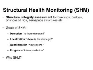
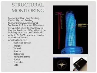
Structural Instrumentation and Monitoring Navigation Lock and Dam Inspection and Emergency Repairs Workshop 19 April 2006 Bruce Barker Information Technology Laboratory, ERDC. Why Instrument Civil Works Structures. As directed by COE regulations and guidance

E N D
Structural Instrumentation and Monitoring Navigation Lock and Dam Inspection and Emergency Repairs Workshop 19 April 2006 Bruce Barker Information Technology Laboratory, ERDC
Why Instrument Civil Works Structures • As directed by COE regulations and guidance • - EM 1110-2-4300, Engineering and Design - Instrumentation for Concrete Structures • - ER 1110-2-103 Strong Motion Earthquake Monitoring • Ensure life-cycle performance of critical structures • Support preventive and predictive maintenance programs for key components • Establish nominal conditions and loads • Provide real-time information or alerts in extreme events or conditions • Replace lost manpower with “automation”
Then Why Don’t We? • The need for instrumentation is seldom recognized…until there is a problem • $$$ - Both from an installation and maintenance standpoint • Lack of maintenance programs for systems can result in poor long-term reliability • Difficult to retrofit existing infrastructure • Bad experiences with data management – over sampling, and lack of automated analysis • Lack of awareness of new technologies that can minimize the above
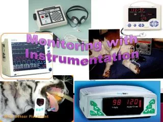
Sensors and Measurement Options Available • Pore Pressures (Piezometers, Pressure cells) • Fluid Velocities (Flow meters) • Displacements (Extensometers, LVDT’s, strain • and crack gages) • Movement (GPS Systems and DGPS ) • Orientation Angle & Tilt (Inclinometers, Tilt • meters) • Dynamic Motions (Accelerometers, Geophones, • Seismographs)
Examples of Structural Instrumentation Projects
Trunnion Anchorage Testing Sep – Nov 2005(Tulsa District) Canton Dam John Redmond Dam Fall River Dam
Trunnion Anchorage Testing Sep – Nov 2005(Tulsa District) The district was concerned that corrosion of the trunion anchorage beams may have significantly weakened the gate support structure. A method was needed to test the condition of the beams Rust Stains indicate possible corrosion of anchor beams
Canton Dam Trunnion Anchor Testing Strain Gage Location Strain Gage Assembly Bolted to I-Beam
D1 S1 S3 S2 S6 S5 S4 D2 Canton Dam - Pier 15 Data Gage Locations
D1 S1 S3 S2 S6 S5 S4 D2 Canton Dam - Pier 16 Data The expectation was that Pier 16 would test “weaker” than Pier 15 – Results were roughly the same Gage Locations
Long-term Monitoring Instrumentation Installed at John Redmond Dam Weldable Strain Trans- ducers were attached to gate girders
Long-term Monitoring Instrumentation Installed at John Redmond Dam CR-1000 Datalogger with cellular interface LVDT Installed on Anchorage Girder
Trunnion Friction Evaluation at Strom Thurmond Dam, GA (Savannah District)
Trunnion Friction Measurement Concept F Girder Laser Target Rotating Laser F Girder
LASER TARGETS Trunnion Friction Evaluation at Strom Thurmond Dam, GA (Savannah District)
Greenup L&D Miter Gate Instrumentation, (Huntington District) Sep- Nov 2003
Miter Gate Repairs • Remove triangular gussets and replace with round gussets • Remove and replace cracked flanges • Heat straighten out-of-plane distortion of thrust diaphragm and girder web • Add stiffeners to thrust diaphragm and girder web • Reset quoin block • Install long term monitoring instrumentation to help understand the source. Return lock to service as soon as possible!
Strain Gage Locations Plan View Upstream Miter End S1 (G15) S2 (G15) S3 (G13) Section U.S. Skin Plate S-C S-A D.S. Flange Girder Web S-B S-D
Strain Gage Locations Plan View Miter End Thrust Diaphragm Section S5-C S5-A U.S. Flange D.S. Flange S5-B Girder Web
Strain Gage Locations Plan View Miter End Skin Plate U.S. Flange Detail S4-C S4-B S4-A Thrust Diaphragm Vertical Flange
Strain Gage Installation HiTech Products Strain Sensor ERDC technician Tommy Carr welding down a strain gage
Cable Protection Cable protection was done with flex tubing and a 1-1/2” conduit run from the top of the gate to the bottom
Data Collection Campbell Scientific CR10X Data logger Installed in gate control building
Example of a Geotechnical Instrumentation Project
Carters Reregulation Dam – Expansive Concrete AAR (Mobile District) Crack at South Abutment
22 Jan 2005 CARTERS REREGULATION DAM PROPOSED INTRUMENTATION LOCATIONS LEGEND LVDT / GAUGE BLOCK TILT-METER BOREHOLE EXTENSOMETER STRING POTENTIOMETER HORIZONTAL EXTENSOMETER
FLEX-CONDUIT (INST. WIRES) CAP FLANGES STANDPIPE 4.83” DIA BORE HOLE GROUT STEEL RODS IN PVC JACKET ANCHOR CARTERS REREG DAM BOREHOLE EXTENSOMETERS 22 Jan 2005 EXTENSOMETER CONCEPT EXTENSOMETER LOCATIONS BOREHOLE (AAR 4-98) BOREHOLE (AAR 3-98) ANCHORS A3 (EL 684) A1 (El 677) A2 (El 653) A4 (EL 659)
Modified RBMD for Automated Displacement Measurement in the Longitudinal Axis Core Extension (Spring Loaded) 4” Aluminum Angle Position Sensor (LVDT) Center Hill Dam - Relative Block Movement Devices (RBMD’s)
LIDAR Survey of the Structure LEICA Model HDS3000 Stated position accuracy of 6-mm @ 50m Uses DGPS position tie into state plane Single point distance accuracy is about 4-mm Uses proprietary software compatible with most CAD platforms. LIDAR survey presented here was conducted by Lowe Engineers, Atlanta, GA
Point cloud rendering of Carters Rereg Dam Cyclone Software (oblique view) Mobile District
CloudWorx Software Plan View Mobile District
Horizontal Slice Elevation 664-665 (2’ above the sill) Gate 1 = 42.000’ Gate 2 = 42.004’ Gate 3 = 42.000’ Gate 4 = 41.909’ Mobile District
Horizontal Slice Elevation 699-700 (37’ above the sill) Gate 1 = 41.875’ Gate 2 = 41.942’ The South Gate Opening was the worst case with a narrowing of almost 3 inches at the pintle level Gate 3 = 41.962’ Gate 4 = 41.862’ Mobile District
Advances in Technology for Structural Monitoring Programs • Fiber optic sensors improve reliability and long term • performance • Robust wireless interfacing and networking reduce • hardwire requirements • Real time access of data through web portals • Digital Smart-Sensors improve accuracy and simplify • maintenance • Distributed “intelligence” at the sensor automate the decision process and reduce data management issues
The future in Long-term Monitoring Instrumentation Internet Protocol IPv6 will offer enormous potential for remote sensing applications, allowing roughly 100 IP addresses for every person on the planet. TinyOS has been developed to enable very small, low power, low cost, network linked sensor platforms.
The Future of Real-time Monitoring Garo K. Kiremidjian, Founder/CEO “Sensametrics, Inc. is developing technology for comprehensive and cost-effective solutions for structural monitoring of civil assets – bridges, large facilities, new construction, dams, levee walls and buildings - aimed at identifying the onset, development, location, and severity of structural vulnerability and damage. Sensametrics’ technology concept is based on a wireless network of devices, or sensing units, for capturing damage/vulnerability information and a decision support software environment for information presentation and analysis.”
Sensametrics’ Sensing Unit • Each sensing unit has the capability to: • Interface to multiple sensors (either internal or external). • Communicate via a wireless mesh network to other units and base. • Process sensor data through embedded vulnerability/damage • assessment algorithms at the sensor. • Transmit processed information or sensor data.