Download
1 / 50
500 likes | 695 Vues
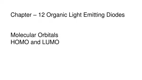
Organic Light Emitting Diodes. (OLEDs). Srivathsa Vaidya. Outline. 1. Chronology of display technology 2. Advantages of LED’s 3. Definition of OLED 4. Principles of operation 5. Technology Branches SMOLED’s LEP’s 6. Effect of dopant 7. Other applications

E N D
Organic Light Emitting Diodes (OLEDs) Srivathsa Vaidya
Outline 1. Chronology of display technology 2. Advantages of LED’s 3. Definition of OLED 4. Principles of operation 5. Technology Branches SMOLED’s LEP’s 6. Effect of dopant 7. Other applications 8. Corporations in this field 9. Conclusion
Basic Idea Behind Emission Molecular Systems Light Energy Emission
Beginning of LED www.kodak.com
Advantages of LED’s over LCD 1. Brighter, thinner, lighter, faster 2. Bright from all viewing angles 3. Need less power to run 4. A lot cheaper to produce 5. Expanding memory capability - coating new layer on top of existing one 6. Wider temperature range 7. Doping or enhancing organic material helps control Brightness Color of light.
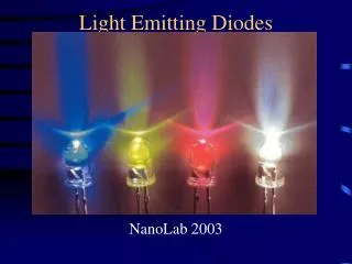
Semiconductor LED’s LED’s work on the principle of injection luminescence. Conventional LEDs are made of : (AlGaAs) - red and infrared (GaAs/P) - red, orange,yellow (GaN) - green (GaP) - green (ZnSe) - blue (InGaN) - blue (SiC) - blue diamond (C) - ultraviolet
OLED is a display device that sandwiches carbon based films between the two electrodes and when voltage is applied creates light. www.ol-ed.com
Single Layer Device Organic electroluminescene (EL) is the electrically driven emission of light from non-crystalline organic materials
HOMO, LUMO of the HTL is slightly above that of the ETL Energy level diagram of a two-layer OLED L.S.Hung et al.,MaterialsScience and Engineering R 39, (2002), 143
- + + S + T S + T S0 + h Chemistry behind Emission Electrons and holes recombine : singlet state, triplet state Formation of triplet is 3 times more feasible than singlet
Photoluminescence vs. Electroluminescence When a radical anion and a radical cation combine on a single conjugated segment, singlet and triplet excited states are formed, of which the singlets can emit light. A.B.Holmes et al., Angew. Chem. Int. Ed. 37, 1998, 402
Factors influencing efficiency • Efficiency of electrons and holes recombination • Efficiency of excited state formation upon annihilation. • Quantum yield of emission of excited state.
1. Light-Emitting Polymers (LEPs) Or Polymer Light Emitting Diode (PLEDs) Using relatively large molecules eg :Conjugated molecules 2. Small Molecule Organic Light Emitting Diodes (SMOLEDs). Using relatively small molecules (even monomers) eg: Metal chelates Two Principle Branches
SMOLEDs Criteria Metal chelates must satisfy • Thermally stable, • Highly luminescent in the solid state, • Thin-film forming upon vacuum deposition • Capable of transporting electrons. C.H.Chen et al., Coordination Chemistry Reviews 171, (1998), 161
Early thin film organic device • Relatively High voltage (80-100 V) - Inject charge into organic crystals • Low work function alloy-cathode • Organic layers, cathode were vacuum deposited. Mg:Ag – 10:1 Luminescent film - 600A Diamine – 750A C.W. Tang & S.A. VanSlyke, Kodak Research Laboratories
Emission Spectrum of the EL Diode. EL emission spectrum is sensitive to thickness of organic layer. Diamine layer transports holes and blocks electrons injected from Mg:Ag electrode.
Brightness-Current-Voltage Characteristics Most of the bias voltage is across AlQ3 EL diode can be driven to produce high brightness.
Key Factors • Morphological properties of organic layers are critical. • Thin films must be smooth and continuous . • Mg is susceptible to atmospheric oxidation and corrosion • Ag improves the sticking coefficient of the metal to the organic layer. • A dc voltage of less than 10V drives the diode.
Full-Color Displays • Development of red, green, and blue emitting electroluminophores • Photophysical properties of Alq3-type complexes are dominated by ligand-centered excited states Pavel Jr.et al., J. Org. Chem. 69, 2004, 1723
Varying degree of electronic density in the quinolinolate ligand, Excitation of dichloromethane solutions at 365 nm.
Preliminary experiments with fabrication of OLED devices The emission maxima of the OLEDs are very close to the maxima recorded in solution • All complexes are electroluminescent • They can be processed via vapor deposition
Other Materials Abhishek et al., Chemistry of Materials, 2004 ASAP
Rules governing the fluorescence of metal chelates (1) Paramagnetic metal ions : Essentially non-fluorescent (2) Increasing atomic number : Fluorescence reduced InQ3 < GaQ3 <AlQ3 (3) Covalent nature of the metal-ligand bonding increased : Emission shifts to longer wavelength.
1.Dendrimers: They are highly branched structures built up from monomer units with precisely controlled architectures. 2. Long chain conjugated molecules: Light Emitting Polymers
R.H.Friend et al., Nature 397, (1999), 121 J.H. Burroughes et al., Nature 347, (1990), 539 Electroluminescent behavior • Semiconducting properties :delocalised -electron bonding • and * orbitals form delocalised valence and conduction wavefunctions, which support mobile charge carriers. • Electrons and holes capture : polymer film • Form neutral bound excited state: Exciton • Due to confinement, energy difference between singlet and triplet may be large.
Perfluorinated Phenylene Dendrimers • Good Electron-transport materials for OLEDs (1) Low-lying LUMOs and HOMOs (2) Relatively low sublimation temperature (3) Good thermal and chemical stability (4) Soluble in CHCl3, THF and aromatic solvents such as toluene. Suzuki et al.,J. Am. Chem. Soc. 122, 2000, 1832
Luminance-voltage characteristics Performance of the devices 3 < 2 < 4 < 5. 2 and 3 (biphenyl)< 4 (p-terphenyl) < 5 (p-quaterphenyl) When the LUMO energy level of the electron-transport material becomes lower, the electron injection from the metal layer to the electron-transport layer should be easier
Perfluorinated Oligo(p-Phenylene)s: PF-5P <1< PF-6P = PF-7P = PF-8P <2
A perfluoro-2-naphthyl group turned out to be an excellent building block for constructing n-type semiconductors • This might indicate that the LUMO level is low enough rate of electron injection is not affected by the LUMO energy • Sophie B. Heidenhain et al.,J. Am. Chem. Soc.122, 2000, 10240
Inorganic semiconductors , organic dyes : deposited sublimation or vapor deposition Fluorescent conjugated polymers : deposited from solution by spin-coating or Langmuir Blodgett technique A.B.Holmes et al., Angew. Chem. Int. Ed. 37, 1998, 402
Multilayer Devices Increase efficiency of devices - electron injection has to be significantly boosted. Electron-conducting/holeblocking (ECHB) layer
Design of ECHB Electron-deficient and poor hole acceptor Work on electron hopping mechanism Fu Wang et al., Adv. Mater. 11, 1999, No. 15
Polymers with higher electron affinity Ideal light-emitting polymer should be both fluorescent and avoid the need for an extra electron-transporting material. Electron-withdrawing groups on the ring or vinylene moiety of PPV A.B.Holmes et al., Angew. Chem. Int. Ed. 37, 1998, 402
Effect of Dopant (Organic Fluorescent dyes) Dyes in solid state suffer from • Quenching • Broadening of emission bands • Bathochromic Shifts Doping fluorescent dye as guest in a host matrix Increase in lifetime Rubrene Peter Baeuerl et al.,J. Mater. Chem., 10, 2000 , 1471
Other applications • FOLED: Flexible OLED • PHOLED :Phosphorescent OLED • TOLED: Transparent OLED • SOLED: Stacked OLED • PMOLED: Passive Matrix OLED • AMOLED: Active Matrix OLED
Future Research Solutions for the following: • Susceptibility towards oxidative degradation • Lifetimes remains lower • Photooxidation produces carbonyl defects that quench fluorescence
Corporations in OLED’s Small Molecule Kodak IBM UDX Ritek Polymer CDT Dupont Philips Dow Chemicals
Conclusion • OLED is a display device that sandwiches carbon based films between the two electrodes and when voltage is applied creates light • SMOLED’s & LEP’s are its technology branches. • Chemical modifications to the structure can tune the emission over the entire visible region. • Multilayer devices and dopants also play a role in tuning emission. The dynamic interplay of chemistry with device physics results in these remarkable displays.
Acknowledgments Prof. Russell.H.Schmehl Group Members : Dr.Sujoy Baitalik Heidi Hester Kalpana Shankar Rupesh Narayana Prabhu David Karam Chemistry Department All of You
Hole-Injection Materials • Anode buffer layer- reduces the energy barrier in-between ITO/HTL. • Enhances charge injection at interface. • CuPc,p-doped aromatic amines,