Download
1 / 13
140 likes | 309 Vues
Arduino Guitar Pedal. Ian Andal IME 458 Dr. Pan. Agenda. Introduction How it works: PCB Schematic Input Pre-amp Stage Arduino Digital Signal Processing Mixer/Output Stage Manufacturing Process Finished Project Results. Introduction.

E N D
Arduino Guitar Pedal Ian Andal IME 458 Dr. Pan
Agenda • Introduction • How it works: • PCB Schematic • Input Pre-amp Stage • Arduino Digital Signal Processing • Mixer/Output Stage • Manufacturing Process • Finished Project • Results
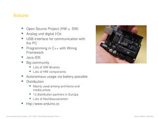
Introduction • Goal of this project is to replicate an Instructables project, the Arduino Guitar Pedal • The Arduino Guitar Pedal is a low-fidelity (lo-fi), multi-effects digital guitar pedal with an Arduino Uno acting as the digital signal processor
Input Pre-amp Stage • The guitar signal goes into the circuit via J1 connector and goes to the TL082 IC (U2) at pin 5 for amplification • R18 ,R14, and C5 makes the op-amp act as an active low-pass filter. • R2 and R9 create a voltage divider to set the reference voltage of 4.5V for the non-inverting inputs of the op-amps.
Arduino Digital Signal Processing • R23 scales the amplified guitar signal and that signal is AC couple to a resistor divider through C9. • The resistor divider shifts the DC level of the guitar signal to around 0.5V • The analog-to-digital converter samples the signal via A0 pin for signal processing
Mixer/Output Stage • The Arduinocreates pulse-width modulated signals that go through C7 for mixing • The pulse-width modulated signals and the clean guitar signal mix in via the second op-amp in the TL082 IC (U2) • This amplified mixed signal goes out to the guitar amp via AC coupling through C3 and the J3 connector.
Design Process • All through-hole components • Circuit mainly consists of resistors, capacitors, and through-hole pads for wires to connect to • Easier assembly process
Results • Guitar pedal functioned as expected; played various programmed guitar effects • Low quality or lagging in performance for certain effects due to: • Memory limitations of the Arduino • Bit resolution of the ADC • Could not fit all the contents into the case due to my miscalculations on the physical dimensions of the PCB and the components
Reference • More information on the Instructable for the Arduino Guitar Pedal can be found here: http://www.instructables.com/id/Arduino-Guitar-Pedal/