Download
1 / 18
200 likes | 462 Vues
Laser Transmitter for the Tropospheric Wind Lidar Technology Experiment (TWiLiTE ) Floyd Hovis, Fibertek, Inc. Bruce Gentry, NASA Goddard Space Flight Center. Laser Transmitter Specifications. Performance Specifications/Design Performance Summary Table. Environmental Design Performance.

E N D
Laser Transmitter for the Tropospheric Wind Lidar Technology Experiment (TWiLiTE)Floyd Hovis, Fibertek, Inc.Bruce Gentry, NASA Goddard Space Flight Center
Laser Transmitter Specifications Performance Specifications/Design Performance Summary Table
Environmental Design Performance Environmental Design Parameters - Laser Optics Module *Assumes thermal interface plate maintained at nominal operating temperature +/-2°C Environmental Design Parameters - Laser Electronics Unit *Assumes liquid cooled interface plate for low pressure operation Design performance exceeds all environmental performance specifications
BalloonWinds, Raytheon, and Air Force Lasers Provided Basis For Key Design Features Three amplifier design Autonomous operation controlled through RS232 serial interface Nominal 28 VDC primary power Space-qualifiable electrical design Thermal control through conductive cooling to liquid cooled plates bolted to bottom of laser module 355 nm single frequency output of >380 mJ/pulse @ 60 Hz (23 W) Deliverable system will undergo extended life testing at Raytheon Electronics module Laser module Space-Winds Lidar Laser Transmitter Final acceptance testing was completed in November 2006
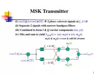
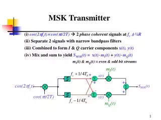
Laser Transmitter Ring Resonator Fiber-coupled 1 mm seed laser Conceptual Optical Layout Optical isolator LBO doubler LBO tripler Power amplifier 532/1064 nm output Fiber port 355 nm output
Laser Housing Baseline DesignFull Assembly Coolant connection • Dual compartment optical cavity • Oscillator and amplifier on opposite sides • I-beam like structure for increased stiffness • No pressure induced distortion of primary mounting plate • Conductively cooling to liquid cooled center plane • Hermetic sealing for low pressure operation Purge port Signal connectors Power connectors Coolant connection
Laser Housing Baseline DesignOscillator Compartment Ring Resonator Purge port 355 nm nm output window Coolant connection 1064 & 532 nm output window
Laser Housing Baseline DesignAmplifier Compartment Amplifier SHG THG Purge port Coolant connection 1064/532 nm output port, external beam dump to be added 355 nm output port, external beam expander to be added
Laser Housing Baseline DesignOscillator Compartment Size Top View • An ~ 31 cm x 25 cm x 14 cm canister accommodates all required optical and electrical components • I-beam like mounting structure provides high mechanical stability • All optical components are mounted to a surface that to first order does not experience pressure induced deformation 31 cm 25 cm Side View 14 cm 31 cm
Ring Oscillator Performance Overview 1 mm Resonator Design Parameters Diode Bars Eight 6-bar arrays, 100 W rated-QCW, operated at 75 W peak power per bar Pulsewidth 56 ms Repetition rate 200 Hz Pump Energy 0.202 J Heat Dissipation 250 watts Slab Size 4.2 x 4.2 x 94 mm3 Doping Level 1.1 % Nd3+ Angle of Incidence 57˚ TIR Bounces 12 per pass Cavity Length 40 cm (physical) Cavity Magnification 1.5 Out-Coupling 40 % Output Pulse Energy 25 mJ OutputPulsewidth 13-15 ns OutputBeam Size ~3 mm super gaussian (variable)
Power Amplifier Design Brewster Angle Slab Design Features Even bounce Brewster angle design reduces beam pointing change due to slab movement Equal number of 10 bar arrays per string (5) simplifies diode driver electrical design Modeling assuming 100 W/bar arrays are operated at 75 W/ bar predicts 100 mJ/pulse output for 25 mJ/pulse input for 63 µs pump pulses Mechanical mounts will be scaled down version of NASA Ozone designs Modeling predicts that extracting a power amplifier with 25 mJ/pulse achieves 100 mJ/pulse output at 1.3 % duty cycle
Third Harmonic GenerationResults Of Fibertek IR&D Type I LBO doubler Type II LBO tripler 1064 nm input 355 nm output /2 @ 1064nm Characterized Type I LBO doubler for higher damage threshold and linearly polarized residual 1064 nm - Damage was an issue in early testing with KTP - LBO damage threshold is ~4X that of KTP - Low cost (relatively), high quality LBO crystals are now commercially available Characterized 25 mm Type II LBO tripler - High quality, low cost (relatively) has recently become available - Ion beam sputtered AR coatings have demonstrated high damage thresholds and low reflectivities for triple AR coatings (1064/532/355 nm) Space-qualifiable laser delivered to Raytheon achieved 23 W of 355 nm for 44 W of 1064 nm pump at 50 Hz (52% conversion efficiency)
Opto-Mechanical Design andProcurement Status • Optical design is complete • Long lead optical components are on order • 808 nm pump diodes • Zigzag slabs for oscillator, preamplifier, and amplifier • Mechanical designs of diode pumped laser heads are complete • Parts have been ordered • Design of laser canister is nearly complete • Some detailing of amplifier optical train and external interfaces remains to be done • Goal is to order canister in February 2007
Electronics Overview • Laser Module electronics • Q-Switch Driver (high-voltage converter, high-voltage switch) • Photo-detector (detects cavity resonance) • SHG/THG Heaters and temperature sensors • Cavity Modulator • Seed Laser & Electronics • Laser Electronics Unit • Power input, filtering, conversion and distribution • Diode Drivers (voltage converter, high-current pulse switching) • Cavity modulator driver (HV power amplifier) • Laser Controller board (pulse timing, system interface, controls) • Temperature Control Boards • Safety Interlocks • All electrical designs were previously developed for the BalloonWinds and Raytheon Wind Lidar laser transmitters
Software Interface Is Complete WARMUP FAULT ARMED LPWR HPWR DIAG Power-up Blue text indicates alternative command characters when operating laser system from HyperTerminal serial interface CNTRL INITIALIZE “1” COLD 1 HPWR 6 CNTRL HPWRMODE “C” CNTRL HPWRMODE ARMED LPWR HPWR DIAG CNTRL HTRSON “C” CNTRL LASERDISARM “4” CNTRL LPWRMODE “D” “A” WARMUP 2 ARMED 4 LPWR 5 CNTRL LPWRMODE CNTRL LASERARM “A” “7” CNTRL STOP CNTRL CLRINT “2” CNTRL DIAGMODE “-” (hyphen) LPWR HPWR DIAG “8” FAULT 3 DIAG 7 WARMUP ARMED LPWR HPWR DIAG Any active fault
Electronics Design and Procurement Status • Software design is complete • Design upgrades to allow high altitude unsealed operation is well underway • Original plan was for commercial power electronics • Laser control board design complete • Power supply design complete • Diode driver design complete • Logic power supply design complete • Safety controller design in work • Updated seeding circuitry in work • Crystal oven controller in work • Key long lead components are on order • High power, high reliability DC/DC converters • High reliability EMI filter modules (MIL-STD-461C & D) • Hermetic capacitors • Electronics are scheduled to be finished in April 2007
Laser Subsystem Summary • Mass • Laser Optics Module - 16 kg (based on current design) • Laser Electronics Unit - ~22 kg (estimated from BalloonWinds, may decrease • Volume • Laser Optics Module - 31 cm x 25 cm x 14 cm = 10,850 cm3 (based on current design) • Laser Electronics Unit - TBD, expected to be somewhat larger than laser • Power • Estimated total 28 VDC power into system is 470 W • Thermal • Estimated total power dissipation is 450 W • Estimated power dissipation Laser Optics Module is 250 W • Estimated power dissipation Laser Electronics Unit 200 W • Laser subsystem delivery in July 2007
Acknowledgements Funding for this program was provided by the NASA Earth Science Technology Office as part of the Instrument Incubator Program