Download
1 / 13
130 likes | 242 Vues
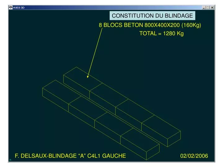
F. DELSAUX-BLINDAGE “A” C4L1 GAUCHE. 02/02/2006. CONSTITUTION DU BLINDAGE. 8 BLOCS BETON 800X400X200 (160Kg). TOTAL = 1280 Kg. F. DELSAUX-BLINDAGE “A” C4L1 GAUCHE. 02/02/2006. CONSTITUTION DU BLINDAGE. 6 BLOCS BETON 350X350X1050 (320Kg). TOTAL = 1920 Kg.

E N D
F. DELSAUX-BLINDAGE “A” C4L1 GAUCHE 02/02/2006 CONSTITUTION DU BLINDAGE 8 BLOCS BETON 800X400X200 (160Kg) TOTAL = 1280 Kg
F. DELSAUX-BLINDAGE “A” C4L1 GAUCHE 02/02/2006 CONSTITUTION DU BLINDAGE 6 BLOCS BETON 350X350X1050 (320Kg) TOTAL = 1920 Kg
F. DELSAUX-BLINDAGE “A” C4L1 GAUCHE 02/02/2006 CONSTITUTION DU BLINDAGE 9 BLOCS BETON 350X350X1050 (320Kg) TOTAL = 2880 Kg
6 BLOCS BETON 350X350X1050 (320Kg) TOTAL = 1920 Kg F. DELSAUX-BLINDAGE “A” C4L1 GAUCHE 02/02/2006 CONSTITUTION DU BLINDAGE
F. DELSAUX-BLINDAGE “A” C4L1 GAUCHE 02/02/2006 CONSTITUTION DU BLINDAGE 9 BLOCS BETON 350X350X1050 (320Kg) TOTAL = 2880 Kg TOTAL DU BLINDAGE = 10880 Kg
F. DELSAUX-BLINDAGE “A” C4L1 GAUCHE 02/02/2006 CONSTITUTION DU BLINDAGE TOTAL DES 3 BLINDAGES EN C4L1 = 32640 Kg
F. DELSAUX-BLINDAGE “A” C4L1 GAUCHE 02/02/2006 PLAN J.P. CORSO DEMI-CELLULE: C4L1 DU 22 AVR 2005 PROPOSITION : POSITIONNER LES BLINDAGES CENTRES SUR LES CHAMBRES A VIDE POUR FACILITER LE SUPPORTAGE ET LIBERER DE L’ESPACE DE TRAVAIL AUTOUR DES POINTS DE CONNECTION DES CHAMBRES NOUVELLE POSITION PROPOSEE POSITION SUR LE PLAN “OPTICAL DRAWING” LHCLSX__0001
F. DELSAUX-BLINDAGE “A” C4L1 GAUCHE 02/02/2006 PLAN J.P. CORSO DEMI-CELLULE: C4L1 DU 22 AVR 2005
F. DELSAUX-BLINDAGE “A” C4L1 GAUCHE 02/02/2006 PLAN J.P. CORSO DEMI-CELLULE: C4L1 DU 22 AVR 2005
F. DELSAUX-BLINDAGE “A” C4L1 GAUCHE 02/02/2006 PLAN J.P. CORSO DEMI-CELLULE: C4L1 DU 22 AVR 2005
F. DELSAUX-BLINDAGE “A” C4L1 GAUCHE 02/02/2006 PLAN J.P. CORSO DEMI-CELLULE: C4L1 DU 22 AVR 2005 DISTANCE ENTRE BLINDAGES = 9600 DISTANCE ENTRE BLINDAGES = 9600 DISTANCE ENTRE LE TAN ET LE BLINDAGE = 8150
F. DELSAUX-BLINDAGE “A” C4L1 GAUCHE 02/02/2006 DEMI-CELLULE: C4L1 DU 02 FEV 2006 COMPRENANT : MAQUETTE BLINDAGES : L0272238MQ MAQUETTE QRL : QRL-C4L1 (BD : LAY1) MAQUETTE VIDE : VIDE-C4L1 (BD : LAY1)
F. DELSAUX-BLINDAGE “A” C4L1 GAUCHE 02/02/2006 SECTION TYPE A CHAQUE EXTREMITE DES 3 BLINDAGES “A”