Download
1 / 22
230 likes | 251 Vues
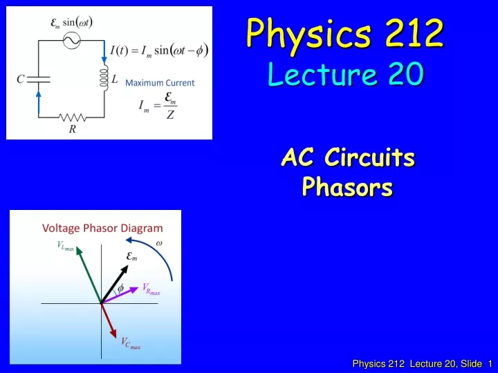
Physics 212 Lecture 20. AC Circuits Phasors. R. Actual current I (t) is the projection of the “phasor” onto the y-axis at time t. V L = LdI/dt. L. 90 o. Inductive “reactance”. Inductor phasor. C. 90 o. Summary. R. C. V max = X C I max. V C 90 o behind I. X C = 1/ w C.

E N D
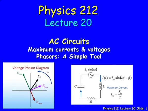
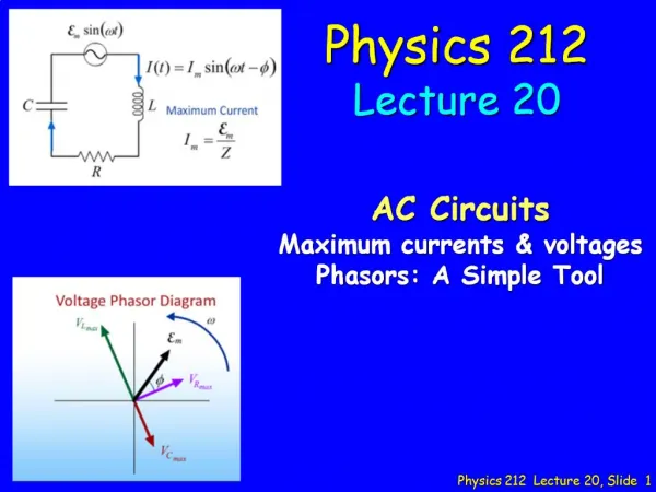
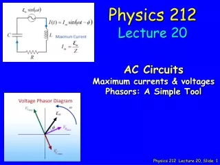
Physics 212 Lecture 20 AC Circuits Phasors
R Actual current I(t) is the projection of the “phasor” onto the y-axis at time t.
VL = LdI/dt L 90o Inductive “reactance” Inductor phasor
C 90o
Summary R C Vmax = XC Imax VC 90o behind I XC = 1/wC L Vmax = XLImax VL 90o ahead of I XL = wL Vmax = R Imax VR in phase with I Current comes first since itcharges capacitor Like a short circuit at highw Like a short circuit at low w
C L R Add phasor voltages around the loop. These add like vectors. If phasors satisfy Khirchoff’s Law, then so will their projections. The projections are the actual voltages.
Imax XC C Imax XL emax L R Imax R Imax XL Imax R Imax(XL-XC) Imax R Imax XC Add component by component.
Imax(XL-XC) Imax R Impedance Phasors (XL-XC) f R Define total circuit impedance Z() emax = Imax Z
Imax XC C Imax XL emax L R Imax R Summary: VCmax= Imax XC VLmax= Imax XL VRmax= Imax R emax = Imax Z Imax =emax / Z (XL-XC) f R
L Imax XL emax R Imax R emax Example: RL Circuit Xc=0 Imax XL Imax R
RL ACT An RL circuit is driven by an AC generator as shown in the figure. L R For what driving frequency w of the generator will the current through the resistor be largest?A) w large B) Current through R doesn’t depend on wC) w small
Imax XL emax Imax R Checkpoint 1a Draw Voltage Phasors A B C
Imax XL emax Imax R Checkpoint 1b Draw Voltage Phasors A B C
Imax XL emax f Imax R f is the phase between generator and current Checkpoint 1c The CURRENT is THE CURRENT A B C D
e IR IXc IXL Checkpoint 2a A B C
IXc IR e Checkpoint 2b A B C IXL
IXc = Vc = Q/C IR e Checkpoint 2c A B C IXL = VL
Calculation C V ~ L R Consider the harmonically driven series LCR circuit shown. Vmax = 100 V Imax = 2 mA VCmax = 113 V The current leads generator voltage by 45o L and R are unknown. What is XL, the reactance of the inductor, at this frequency? • Conceptual Analysis • The maximum voltage for each component is related to its reactance and to the maximum current. • The impedance triangle determines the relationship between the maximum voltages for the components • Strategic Analysis • Use Vmax and Imax to determine Z • Use impedance triangle to determine R • Use VCmax and impedance triangle to determine XL
Calculation C V ~ L R IR 45o V VL VR (phase of current) V leads VC Consider the harmonically driven series LCR circuit shown. Vmax = 100 V Imax = 2 mA VCmax = 113 V The current leads generator voltage by 45o L and R are unknown. What is XL, the reactance of the inductor, at this frequency? Compare XL and XC at this frequency: (A) XL < XC (B) XL = XC (C) XL > XC (D) Not enough information • This information is determined from the phase • Current leads voltage VL = ImaxXL VC = ImaxXC
Calculation C V ~ L R Consider the harmonically driven series LCR circuit shown. Vmax = 100 V Imax = 2 mA VCmax = 113 V The current leads generator voltage by 45o L and R are unknown. What is XL, the reactance of the inductor, at this frequency? What is Z, the total impedance of the circuit? (A) (B) (C) (D) 50 kW 35.4 kW 70.7 kW 21.1 kW
Calculation C V ~ L R • Determined from impedance triangle R R = Z cos(45o) 45o (XC-XL) = 50 kW x 0.707 Z=50kW = 35.4 kW Consider the harmonically driven series LCR circuit shown. Vmax = 100 V Imax = 2 mA VCmax = 113 V The current leads generator voltage by 45o L and R are unknown. What is XL, the reactance of the inductor, at this frequency? Z = 50kW sin(45)=.707 cos(45)=.707 What is R? (A) (B) (C) (D) 70.7 kW 35.4 kW 21.1 kW 50 kW
Calculation C V ~ L R We start with the impedance triangle: XL = XC - R R 45o (XC-XL) Z XL = 56.5 kW – 35.4 kW Consider the harmonically driven series LCR circuit shown. Vmax = 100 V Imax = 2 mA VCmax = 113 V The current leads generator voltage by 45o L and R are unknown. What is XL, the reactance of the inductor, at this frequency? Z = 50kW R = 35.4kW (A) (B) (C) (D) 70.7 kW 35.4 kW 21.1 kW 50 kW What is XC ? VCmax = ImaxXC