Download
1 / 39
390 likes | 521 Vues
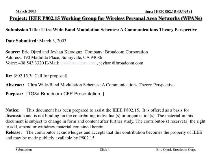
Project: IEEE P802.15 Working Group for Wireless Personal Area Networks (WPANs) Submission Title: Ultra Wide-Band Modulation Schemes: A Communications Theory Perspective Date Submitted: March 3, 2003 Source: Eric Ojard and Jeyhan Karaoguz Company: Broadcom Corporation

E N D
Project: IEEE P802.15 Working Group for Wireless Personal Area Networks (WPANs) Submission Title:Ultra Wide-Band Modulation Schemes: A Communications Theory Perspective Date Submitted: March 3, 2003 Source: Eric Ojard and Jeyhan Karaoguz Company: Broadcom Corporation Address: 190 Mathilda Place, Sunnyvale, CA 94086 Voice: 408 543 3320 E-Mail: eo@broadcom.com, jeyhan@broadcom.com Re: [802.15.3a Call for proposal] Abstract: Ultra Wide-Band Modulation Schemes: A Communications Theory Perspective Purpose: [TG3a-Broadcom-CFP-Presentation.] Notice: This document has been prepared to assist the IEEE P802.15. It is offered as a basis for discussion and is not binding on the contributing individual(s) or organization(s). The material in this document is subject to change in form and content after further study. The contributor(s) reserve(s) the right to add, amend or withdraw material contained herein. Release: The contributor acknowledges and accepts that this contribution becomes the property of IEEE and may be made publicly available by P802.15. Eric Ojard, Broadcom Corp.
Ultra-Wide-Band Modulation SchemesA Communications Theory Perspective Eric Ojard Broadcom Corporation
Introduction • This presentation is a tutorial on some of the options available in designing a PHY protocol for UWB • Key questions: • Channelization for uncoordinated piconets: Frequency Division or Code Division? • How much bandwidth should we use? • Coding Scheme • Modulation & Spreading Options • Various options are considered and the trade-offs are analyzed Eric Ojard, Broadcom Corp.
Constraints and Requirements • FCC allows use of 3.1-10.6 GHz at –41 dBm/MHz • 802.15.3 SG3a Target Rates • 110 Mbps @ 10 m required • 200 Mbps @ 4 m required • 480 Mbps @ 1m desired • Should operate in the presence of 3 other uncoordinated piconets (requires some type of channelization) Eric Ojard, Broadcom Corp.
Outline • Theoretical Capacity in Low-SNR regime • Coding & Spreading Examples • Uncoordinated Piconets: Frequency Division vs Code Division • Bandwidth Usage • Code Division Spreading Options Eric Ojard, Broadcom Corp.
Theoretical Capacity slope: 1 bit/s/Hz per 3 dB log2(1+SNR) SNR log2(e) slope: 2X per 3 dB 2(1-H(Q(sqrt(SNR)))) Eric Ojard, Broadcom Corp.
Theoretical Capacity (cont’d) • The graph can be divided into two distinct regions: • High SNR regime (SNR > 0 dB or C > 1 bit/s/Hz) e.g. 802.11a/b/g, 802.15.3 • Low SNR regime (SNR < 0 dB or C < 1 bit/s/Hz) e.g. UWB • The curves behave differently in the low-SNR and high-SNR regimes: • At high SNR, capacity increases by 1 bit/s/Hz for every 3 dB • At low SNR, capacity increases by a factor of 2 for every 3 dB • Coding has a much bigger payoff in the low-SNR regime than in the high-SNR regime. • At low SNR, binary modulation is optimal – nothing to be gained from higher-order constellations. • In theory, very high rates are achievable at very low SNR: • @ -10 dB, 7 GHz * 0.15 bits/s/Hz = 1 Gbit/s • @ -13 dB, 7 GHz * 0.075 bits/s/Hz = 500 Mbps • @ -16 dB, 7 GHz * 0.037 bits/s/Hz = 250 Mbps Eric Ojard, Broadcom Corp.
*plots generated by function ~/research/uwb/low_snr_cap_plots.m Theoretical Capacity (cont’d) ½ log2(1+SNR) 1-H(Q(sqrt(SNR))) 10log10(p/2)=1.96 dB 10*log10(ln(2))=-1.59 dB Another way of viewing the same curves: Eb/N0=SNR/2R Eric Ojard, Broadcom Corp.
Coding & Spreading • The previous slides showed only the Theoretical Capacity. • At low SNR, reduce rate by 2X for every 3 dB from the Shannon limit. • It is straightforward to combine well-known binary codes with spreading sequences, as shown in the following slides. • easy to get within 6 dB of Shannon limit using convolutional codes • possible to get much closer to Shannon limit using concatenated codes and/or iterative decoding. Eric Ojard, Broadcom Corp.
Coding & Spreading Examples of well-known codes combined with spreading no spreading spreading *code plots assume optimal soft-input decoding Eric Ojard, Broadcom Corp.
Coding & Spreading Examples of well-known codes combined with spreading (another way of viewing the same data) no spreading spreading *code plots assume optimal soft-input decoding Eric Ojard, Broadcom Corp.
Channelization Options • The solution should support 4 uncoordinated piconets (02/104r15) • Channelization Options: • Code Division Multiplexing (CDM) • Frequency Division Multiplexing (FDM) • FDM: 4 non-overlapping frequency bands: • 6 dB penalty in transmitted power • Additional path loss penalty for high-frequency channels: 20 log10(4pfc/c) dB • Potential for better performance compared to CDM in cases where uncoordinated piconets are very close • Lost immunity to frequency-selective fading is minor (see slides on fading vs bandwidth) • CDM: Each piconet has a different spreading code • allows use of maximum transmitted power • maximum immunity to frequency-selective fading Eric Ojard, Broadcom Corp.
Link Margin: FDM vs. CDM • In the following slides, we consider two cases: • (1) FDM: fmin=8.725 MHz, fmax=10.6 MHz (highest-freq channel in a 4-channel system) • PT = -8.27 dBm • L1 = 52.10 dB • (2) CDM: fmin=3.1 MHz, fmax=10.6 MHz • PT = -2.25 dBm • L1 = 47.61 dB Reference: IEEE P802.15-02/490r0-SG3a Eric Ojard, Broadcom Corp.
*plots generated by function ~/research/uwb/link_margin_plots.m Link Margin • From a coding perspective... • 480 Mbps @ 1m is very easy • 200 Mbps @ 4m is harder • 110 Mbps @ 10m is the hardest • The FDM system* requires ~10.4 dB more coding gain than CDM. *highest frequency band: 8.725-10.6 GHz Eric Ojard, Broadcom Corp.
Link Margin: FDM vs CDM • (1) FDM: fmin=8.725 GHz, fmax =10.6 GHz (highest frequency channel) • requires S+I <= 6.2 dB for 110 Mbps @ 10 m • requires strong code & near-optimal receiver • very little margin • not impossible, but very demanding. • (2) CDM: fmin=3.1 GHz, fmax =10.6 GHz • requires S+I <= 16.7 dB for 110 Mbps @ 10 m • Very easy, even with weak code & high implementation loss. Eric Ojard, Broadcom Corp.
*plots generated by function ~/research/uwb/piconet_interference_plots.m Uncoordinated Piconets w/ CDM dref dint Desired Transmitter Receiver Interfering Transmitter • Assume uncoordinated piconets use the same frequency band with different spreading codes. • Assume true orthogonality isn’t practical due to random multipath & lack of synchronization. • Treat interference as uncorrelated noise with same PSD as desired signal. Eric Ojard, Broadcom Corp.
Uncoordinated Piconets w/ CDM • For a CDM system operating within 9 dB of the Shannon Limit, the target rate of 110 Mbps can be met @ dref/dint=3.3 • Although strong codes aren’t needed to meet the basic requirements in an interference-free environment, coding gain & receiver performance (S+I) will have a large impact on performance in self-interference environments. • dref/dint increases by 2X per 6 dB of coding gain • Regardless of coding gain, CDM systems will never allow uncoordinated piconets “on top” of each other (“near-far problem”). • In theory, FDM could perform much better when uncoordinated piconets are very close.* *FDM isn’t the only way to achieve this. This can be achieved by any method that results in truly orthogonal signals (including multipath effects) at the receiver. Eric Ojard, Broadcom Corp.
How Much Bandwidth Should We Use? • Pros of wider bandwidth: • Under the FCC’s UWB regulations, transmit power is proportional to the bandwidth. • But note that the net benefit on link margin is reduced at high frequencies due to L1=20*log10(sqrt(4pfminfmax)) • In a self-interference environment (e.g. uncoordinated piconets using same frequency band)... • the achievable rate is proportional to the bandwidth. • for a given target rate, dref/dint ~ sqrt(BW) • Better Immunity to Frequency-Selective Fading • Cons of wider bandwidth: • typically results in higher cost, power. Eric Ojard, Broadcom Corp.
Bandwidth & Fading • One of the key advantages to Ultra-Wide-Band technology is its inherent immunity to frequency-selective fading. • Narrowband signals cannot resolve multipath components; the entire frequency band could fall in a deep spectral null. • The immunity to fading is a function of the ratio of bandwidth to center frequency. ~18 dB ~20 MHz Example Channel: 20 MHz channel can have 15-20 dB fade. Eric Ojard, Broadcom Corp.
*plots generated by function ~/research/uwb/bw_fade_test.m Fading Probability vs. Bandwidth CM1 CM2 Eric Ojard, Broadcom Corp.
*plots generated by function ~/research/uwb/bw_fade_test.m Fading Probability vs. Bandwidth (cont’d) CM3 CM4 Eric Ojard, Broadcom Corp.
Bandwidth & Fading (cont’d) • 15 MHz -> 5 GHz: reduction in 1% worst-case fade: • CM1: 15 dB • CM2: 12 dB • CM3: 12 dB • CM4: 9 dB • Not much difference between 1.5 GHz curves and 5 GHz curves: anything with BW > ~1 GHz has good fading immunity. • The accuracy of these results is highly dependent on the accuracy of these channel models. Eric Ojard, Broadcom Corp.
Spreading & Modulation Options • Here we consider modulation schemes where uncoordinated piconets share the same frequency band (CDM) • Several possible variations on DSSS* (not an exhaustive list) • Long PN Spreading Sequence • Symbol-Length Spreading Sequence • Multi-Symbol-Length Spreading Sequence • Symbol-Length Spreading with Short Time Hopping *DSSS = Direct Sequence Spread Spectrum Eric Ojard, Broadcom Corp.
Long Sequence Spreading • Chip sequence is a long (effectively infinite length) pseudo-noise sequence. • Every symbol has a different spreading sequence. • Every uncoordinated piconet has a different spreading sequence. • Advantages • Perfect autocorrelation properties (flat PSD) • Perfect cross-correlation properties with uncoordinated piconets. • Disadvantages • Near-optimal detection requires a high complexity receiver for a large number of multipath components. • Any additional ISI mitigation requires a more sophisticated receiver design Eric Ojard, Broadcom Corp.
Symbol-Length Spreading (SLS) Sequence • The chip sequence is the same for every symbol. • Linear Time Invariant (LTI) modulation • Advantages • Lower-Complexity receiver • Disadvantages • Imperfect Autocorrelation: PSD has ripple (assuming binary spreading sequences) • Imperfect Cross-correlation with uncoordinated piconets. • Random multipath tends to provide low correlation, but this breaks down in free-space. • Trade-off between autocorrelation and cross-correlation becomes harder to manage at higher symbol rates. Eric Ojard, Broadcom Corp.
Symbol-Length Spreading w/ Time-Hopping • The chip sequence is the same for every symbol. • To reduce the correlation with uncoordinated piconets, symbol positions are dithered by a pseudo-random hopping pattern. • Better Cross-correlation properties compared to plain Symbol-Length Spreading. • Time-varying ISI makes optimal detection more complex. Eric Ojard, Broadcom Corp.
Multi-Symbol-Length Spreading Sequence • The chip sequence repeats every N symbols, where N is a small integer. • Better auto-correlation and cross-correlation properties compared to symbol-length spread-spectrum. • Higher Complexity Detection than Symbol-Length Spreading • Time-varying ISI makes optimal detection more complex. Eric Ojard, Broadcom Corp.
Comparison of DSSS variations Eric Ojard, Broadcom Corp.
Conclusions • In Theory, the UWB environment enables rates far in excess of the target rates. • Supporting 4 uncoordinated piconets is the biggest challenge. • FDM would require very strong coding to meet the target rates, but could perform better when uncoordinated piconets are very close. • CDM could meet target rates with weaker coding, but performance would be limited when uncoordinated piconets are close. • Wider bandwidth always enables higher performance... • especially when uncoordinated piconets share the same frequency band • but at the expense of higher complexity. Eric Ojard, Broadcom Corp.
Backup Slides Eric Ojard, Broadcom Corp.
Channel Models • The proposed channel model for simulations is described in 802.15-02/368r5. • 3 parts: • Path loss Model • Multipath Model • Shadowing Model Eric Ojard, Broadcom Corp.
Path Loss Model L = 20*log10(d) dB, where d is in meters Eric Ojard, Broadcom Corp.
Multipath & Shadowing • The Multipath Model is a Saleh-Valenzuela model, modified so that multipath gains have a lognormal distribution rather than a Rayleigh distribution. • 4 Multipath Parameter Sets: • CM1: 0-4m LOS • CM2: 0-4m NLOS • CM3: 4-10m LOS • CM4: 4-10m NLOS • Shadowing: log-normal shadowing with 3 dB standard deviation. Eric Ojard, Broadcom Corp.
*plots generated by function ~/research/uwb/channel_plots.m Example Channels (CM1 & CM2) CM1: 0-4 m LOS CM2: 0-4 m NLOS Eric Ojard, Broadcom Corp.
*plots generated by function ~/research/uwb/channel_plots.m Example Channels (CM3 & CM4) CM3: 4-10 m LOS CM4: extreme NLOS Eric Ojard, Broadcom Corp.
*plots generated by function ~/research/uwb/channel_plots.m Multipath Model Power-Delay Profiles Eric Ojard, Broadcom Corp.
Coding & Spreading @ Pe=1e-8 Examples of well-known codes combined with spreading no spreading spreading *for Pe=1e-5, shift points left by ~2 dB Eric Ojard, Broadcom Corp.
*plots generated by function ~/research/uwb/piconet_interference_plots.m Uncoordinated Piconets w/ CDM dref dint Desired Transmitter Receiver Interfering Transmitter • Assume uncoordinated piconets use the same frequency band with different spreading codes. • Assume true orthogonality isn’t practical due to random multipath. • Treat interference as uncorrelated noise with same PSD as desired signal. Eric Ojard, Broadcom Corp.
Uncoordinated Piconets w/ CDM • For a CDM system operating within 9 dB of the Shannon Limit, the target rate of 110 Mbps can be met @ dref/(dref+dint)=0.77 • Although strong codes aren’t needed to meet the basic requirements in an interference-free environment, coding gain & receiver performance (S+I) will have a large impact on performance in self-interference environments. • Regardless of coding gain, CDM systems will never allow uncoordinated piconets “on top” of each other (near-far problem). • In theory, FDM could perform much better when uncoordinated piconets are very close.* *FDM isn’t the only way to achieve this. This can be achieved by any method that results in truly orthogonal signals (including multipath effects) at the receiver. Eric Ojard, Broadcom Corp.