Download
1 / 18
190 likes | 377 Vues
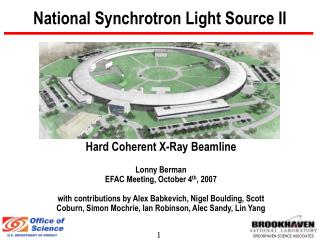
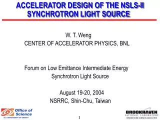
The Implementation of Top Up Operation at the Australian Synchrotron Light Source. Don McGilvery. The Australian Synchrotron Light Source. 3 rd Generation Synchrotron Light Source with a full energy injection system.

E N D
The Implementation of Top Up Operation at the Australian Synchrotron Light Source Don McGilvery
The Australian Synchrotron Light Source • 3rd Generation Synchrotron Light Source with a full energy injection system. • Beam lines tangential to the electron beam collect Synchrotron radiation over the spectral range up to 100KeV X-rays. The Beamline enclosure X-ray shielding is only designed to shield this energy range. • The Storage ring is normally filled to 200mA and with the usual ~30hr beam lifetime requires refilling every 12hrs. • Each Beamline has Safety Shutters which are closed during injections to protect against possible stray electrons or gamma radiation finding their way down a beam line. • User experiments are disrupted during injections • The variation in heat loading, both on the storage ring and beam line optics introduces significant variation in beam flux and beam quality delivered to the end station experiments.
Top Up Operation (Top Off) • Every few minutes a shot of electrons are injected into the storage ring to maintain a near constant photon flux for the beam lines. • The Beamline Safety Shutters remain open during injections. • It is necessary to ensure that no electrons or gamma radiation can find their way down a beam line under both normal operation or possible fault condition. • Modeling the electron orbits during normal operation is relatively easy but predicting all fault conditions to model is rather difficult.
Top Up Operation (Top Off) • We modeled the trajectories electrons or gamma would have to follow to navigate the shielding down a beam line. • We then modeled a restricted range of conditions around normal operations and checked to ensure there was no overlap with the paths down a beam line. • If the storage ring orbits are outside of this range then injections would become interlocked. Phase space of stored beam } Phase space down beamline
Implementing Top Up Interlocks • Only if the Safety Master Shutter is Enabled do we need to protect injection. • We need to ensure that we have the correct electron Beam Energy – Storage Ring (SR) dipole magnets and dipoles in the Booster to Storage (BTS) ring transfer line. • Stored Beam Current > 50mA – if there is stored beam then the orbit is stable • Stored Beam lifetime > 20hrs – good lifetime means reasonable orbit • Correct Orbit – if all of the storage ring quadrupole and sextupole magnets are set to the correct values for the “model orbit” • Injection efficiency > 50% (BTS to SR) Software interlock • Injection efficiency > 30% (Booster to SR) PLC interlock
Gun Interlock System • The electron gun transmitter is controlled via a hardwired Programmable Logic Controller (PLC) based interlock. • Introduced Gun modes which are selected via Software • By default the Gun is “Disable” unless the requested Gun mode is allowed based on the input signals to the PLC • A truth table in the PLC determines which gun modes can be active dependant on the state of the Safety Master Shutter Enable. • Illegal Gun modes cannot enable the Gun. • Single shot modes immediately drop back to disable after the shot is fired • The Top up Software processes also independently monitor all Top up variables and provide a software gun interlock Gun Trigger e- Enable Gun Mode PLC Status Safety Shutter Status
PLC based interlock system • The Equipment Protection PLCs are utilised to control the Electron Gun enable and are linked to the PSS RF inhibit. • There are 7 PLCs connected via a private redundant fibre network. One PLC monitors the other 6 via regular heartbeat signals. It also monitors the link to the Personnel Safety System (PSS). Should any fault occur in these systems the Storage Ring RF is immediately inhibited dumping the stored beam. This is the primary Equipment Protection Network and provides a reliable platform to support Top Up. • The PLCs also monitor via regular heartbeat signals, the IOC processes supporting Top up operation and should any fail, the electron gun is inhibited and Top up operation is suspended. • The PLCs have voltage inputs monitoring the SR Dipole, the 4 BTS dipoles and all of SR quadrupole and sextupole magnets. There are defined ranges set for each of these magnets in the PLC configuration and these limits are set by the Top up Change Control Board.
PLC interlock system cont. • A PLC also monitors the SR current and will not enable the Electron Gun if the Master Shutters are enabled unless the SR current exceeds 50mA. • SR lifetime and injection efficiency are also provided to the PLCs from the Top up IOC processes and will also inhibit the gun in Top up modes. • Previously the electron gun could be fired at any time independent of the state of the Safety Master Shutter enable and relied purely on administrative procedures (Operators) for safe operation. • The implementation of the Gun Interlock system has caused some issues with Machine Studies and requires us to consider “protected injection system operation”.
Magnet Interlocking • Magnets are interlocked both on Current and Voltage • Soft interlocking by Software uses the magnet currents read via the machine network. This was initially implemented to test the Top up before the hardware system was complete. • It has been retained and implements tighter limits on magnet settings and provides a level of redundancy. These limits can be varied if required without approval by the Change Control Board • Hard interlocks use an independent voltage output of the power converters hardwired directly to PLC inputs. • Using voltage rather than current protects against magnet shorts as well as incorrect set points. These limits require approval by the CCB for change. • All Storage Ring quadrupole and sextupole magnets are interlocked ensuring that the electron orbit in the storage ring is within predefined limits, and does not rely on purely administrative control
Injection Efficiency • Any electrons lost during injection can contribute to higher radiation levels around the facility • We do not interlock on “high” radiation • We do interlock on poor electron capture • Electrons are injected into the storage ring off axis and damp via synchrotron radiation over milliseconds • In vacuum insertion devices can be very close to the beam • We use apertures and scrapers to restrict the physical beam size • Injection system optimisation is very critical • Injection system stability is very critical • We interlock on efficiency levels approved by the CCB (50%, 30%) • We are always striving to improve injection efficiency (ALARA)
Code Protection • The Control system is only as reliable as the code which runs it and the level of rigor applied during testing. • In order to provide a high level of code protection both the Software code and PLC code are contained within the CCB envelope. • The computers hosting any Top up code are contained within a “mini-build” separately managed on our version control system. There are restricted rights to modify the code and any Process Variables (PV) associated directly with Top up control. • The control PVs are located on a single concise Graphical User Interface Pane with EPICS restricting ad-hoc changes. The standard Top up configuration files are located in a read-only (restricted write) directory on the server. • The PLCs have password protection to only allow code or limit changes after approval of the CCB. • Any code changes require revalidation of the Top up interlock system.
Pre Run Top up Testing • Before the start of any Top up run a standard test procedure is completed. • This is defined by a test template in the eLog system which once signed off cannot be changed. • Load configuration • Test various interlocks • Optimise machine performance
Timing Interlocks To Beamlines • We provide both low and high resolution interlock signals to the Beamlines. • At present we operate in a current based mode. A target current is set for the machine and whenever the SR beam current is predicted to drop below that target a new injection sequence is initiated. • A routine predicts when the next shot will occur and updates each second the expected next injection time. The XFM beamline uses this countdown to pause or discard data collection during the injection. • Once this countdown reaches 15 seconds the injection time is locked in and a 10 second event is sent to the IR beamline to gate out their data collection. • Each beamline has an event receiver system which they could use to mask injection events but only mid IR uses it.
Top Up Performance Maintaining 200mA +/- 0.5mA over 12hrs
Top Up Shift Summary • A shift summary from eLog. • There was a injection system problem which caused a 43 minute outage of top up.
Summary • Implementation of Top Up has required us to implement a system where we are confident that electron injections into the storage ring can be done safely with the shutters open. • Hardware and Software systems monitor and protect against component or configuration failure. • Hardware systems monitor software systems and variables • Where possible redundant interlocks are implemented. • Software, hardware and configurations are under independent review and control. • The system works well and has not significantly increased Operator work load. • The Beamline Science staff and Users are Very Happy.
Greg LeBlanc – Head Accelerator Physics Dean Morris – Head Operations David Zhu – Physicist (modelling) Andrew Starritt – Controls Engineer (Software) Bryce Karnaghan – Controls Engineer (PLC) Sergio Constantin - Radiation Safety Officer Operators – development, testing and operation Electrical and Mechanical Engineers and Technicians Vince Kempson – External Review The whole operations Team