Download
1 / 31
310 likes | 505 Vues
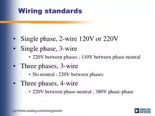
Facility Wiring TDR. Overview. Guided - wire Unguided - wireless Characteristics and quality determined by medium and signal For guided, the medium is more important For unguided, the bandwidth produced by the antenna is more important Key concerns are data rate and distance.

E N D
Overview • Guided - wire • Unguided - wireless • Characteristics and quality determined by medium and signal • For guided, the medium is more important • For unguided, the bandwidth produced by the antenna is more important • Key concerns are data rate and distance
Design Factors • Bandwidth • Higher bandwidth gives higher data rate • Transmission impairments • Attenuation • Interference • Number of receivers • In guided media • More receivers (multi-point) introduce more attenuation
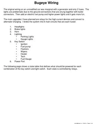
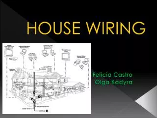
Wiring Closet • Orderly Cable Layout • Can include all of the following: • Network equipment • Fiber optic cables, CAT5 • WAN connections • LAN distribution • Electrical • Video / Cable TV • Telephone • Alarm systems: intrusion, fire, door
Wiring Closet • Orderly Cable Layout Needs HELP!!!!!
Wiring Closet • Orderly Cable Layout
Time Domain Reflectometer • Works by transmitting a pulse of energy into a cable • Observing that energy as it is reflected by the system
Time Domain Reflectometer • Blind Spot • Width of pulse • Speed reduced based on media type
Time Domain Reflectometer • Distance vs. VOP • Velocity of Propagation – speed of light • Speed of light in vacuum = 299,792,458 m/s ( C ) • VOP varies in different media – presented as a % • Distance pulse travels (D) = C x Time (T) D=C*T ; T = D/C • Measured time from transmission of pulse to receipt of reflected pulse – calculate distance • Round trip delay 0.000667128 sec * 299,792,458 m/s = 200,000 • Length = 200,000 / 2 = 100,000 meters • Speed reduced based on media type
Time Domain Reflectometer • Distance - Time T = D/C
Time Domain Reflectometer • VOP for various media • Important for VOP to be accurate • Measured or Obtained from MFR
CABLE TYPE Examples of VOP TYPE VOP TELEPHONE 19AWG Gel-Filled 68 22 AWG Gel-Filled 66 24 AWG Gel-Filled 62 26 AWG Gel-Filled 60 19 AWG AIR 72 22 AWG AIR 67 24 AWG AIR 66 26 AWG AIR 64 Polyethylene 66 Polypropylene 66 Teflon 69 PIC 67 Pulp 72 CATV Belden Foam 78S-82 Solid 66 Comm/Scope (F) 82 PARA I 82 PARA III 87 QR 88 Time Domain Reflectometer
A reflection with the same polarity indicates a fault with OPEN (high impedance) tendencies. The reflection shown at the second cursor is a COMPLETE OPEN.
A reflection with the opposite polarity indicates a fault with short (low impedance) tendencies. The reflection shown at the second cursor is a DEAD SHORT.
The middle reflection at the second cursor is a PARTIAL OPEN followed by a COMPLETE OPEN (end of the cable). The more severe the fault, the larger the reflection will be.
The middle reflection at the second cursor is a PARTIAL SHORT followed by a COMPLETE OPEN (end of the cable). The more severe the fault, the larger the reflection will be.
Two sections of coaxial cable with a barrel connector shown at the second cursor. The amount of reflection caused by the connector is directly proportional to the quality of the connector and connection.
Coaxial taps (both indoor and outdoor) will cause reflections along the waveform. The quality and value of each tap determines the amount of reflection.
A splitter or directional coupler can be identified although accurate measurements are difficult due to multiple reflections. The second cursor identifies the splitter. The two reflections following are the ends of each of the two segments.
A water soaked cable will display a waveform with a downward slope indicating the beginning of the water and an upward rise at the end of the water . Generally, the area in between the two reflections will appear "noisy".
Pulse Waveform 2 - Medium Pulse Width The width of the output pulse is also referred to as the blind spot or dead zone. It is more difficult to "see" a fault when it is contained within the blind spot.
Time Domain Reflectometer • http://www.tscm.com/riserbond.html • http://www.nuvotechnologies.com/pdf/crimping.pdf • http://www.pcnineoneone.com/howto/cat5diy1.html • http://www.commserv.ucsb.edu/infrastructure/standards/history/EIA-TIA_568.asp#Four-pair