Download
1 / 22

E N D
1. BIOGASTECH 9th to 11th April 2008, Gebze/Istanbul, Turkey 1 Cold model testing of an internal circulating fluid bed gasifier
2. 2 1 MWth INTERNAL CIRCULATING FLUID BED GASIFIER
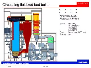
3. BIOGASTECH 9th to 11th April 2008, Gebze/Istanbul, Turkey 3 Internal circulating fluid bed reactor
4. BIOGASTECH 9th to 11th April 2008, Gebze/Istanbul, Turkey 4 Gasifier in ENEA- Trisaia
5. BIOGASTECH 9th to 11th April 2008, Gebze/Istanbul, Turkey 5 Steam-oxygen gasifier
6. BIOGASTECH 9th to 11th April 2008, Gebze/Istanbul, Turkey 6 Requirments are:
? geometric symilarity
Equality of dimensionless number between
cold model and gasifier
? De = r/rp
? Ar = (dp3 rp ( rp � r) g)/m2
? Fr = U/(gL)0.5
7. BIOGASTECH 9th to 11th April 2008, Gebze/Istanbul, Turkey 7
8. 8 Materials for the dynamic similarity
9. 9 Cold model
10. 10
11. BIOGASTECH 9th to 11th April 2008, Gebze/Istanbul, Turkey 11 Experimentals
Measure of the minimal fluidization rate
Measure of the pressure drop at the bottom of the two chambers at different fluidization conditions
Recirculation tests of the glass spheres at different fluidization conditions in the two chamber
Measure of times spent by the spheres in the up-flowing chamber
Recirculation tests of the spheres varying the height of the bottom orefice
12. 12 Minimal fluidization rate
13. 13 Pressure drop between the chambers
14. 14 Recirculation test of the glass spheres at different fluidising condition in the two chambers, were executed simultaneously feeding one hundred glass spheres in the down-flowing chamber and storing their recirculation time, throughout the interconnecting bottom window (having height of 3cm), from the down-flowing chamber to the up-flowing chamber, and from this latter to the first jumping the separating plate. When the spheres returned in the down flowing chamber a metallic holed basket, welded to separating plate, stopped their run, without interfering with the fluidizing phenomena
15. BIOGASTECH 9th to 11th April 2008, Gebze/Istanbul, Turkey 15 Recirculation tests at Udfc =1.7 Umf
16. BIOGASTECH 9th to 11th April 2008, Gebze/Istanbul, Turkey 16 Recirculation tests at Udfc =1.5 Umf
17. 17 Times spent by the spheres in the up-flowing chamber Measure of the times of jumping of twenty spheres over the separating plate from the bottom of up-flowing chamber to the down-flowing chamber for different fluidising condition in the two chambers. Also in these tests a metallic holed basket was used to stop the spheres
18. 18 Spheres path in the cold model
19. BIOGASTECH 9th to 11th April 2008, Gebze/Istanbul, Turkey 19 Build-up gasifier
20. 20 Recirculation tests varying bottom window area
21. 21 Theoretical bed particles flow through an orefice Ws = Cso ecfa2.35*(2rdfcDP)0.5 Kuramoto, kunii eq.
Cso = 0.1
eufc = dufc + (1- dufc) emf
rdfc= r (1- edfc)
edfc = ddfc + (1- ddfc) emf
22. 22 Conclusions