Download
1 / 127
1.29k likes | 1.52k Vues
Embedded System HW. Why use microprocessors?. Alternatives: field-programmable gate arrays (FPGAs), custom logic, etc. Microprocessors are often very efficient: can use same logic to perform many different functions. Microprocessors simplify the design of families of products.

E N D
Why use microprocessors? • Alternatives: field-programmable gate arrays (FPGAs), custom logic, etc. • Microprocessors are often very efficient: can use same logic to perform many different functions. • Microprocessors simplify the design of families of products.
The performance paradox • Microprocessors use much more logic to implement a function than does custom logic. • But microprocessors are often at least as fast: • heavily pipelined; • large design teams; • aggressive VLSI technology.
Power • Custom logic is a clear winner for low power devices. • Modern microprocessors offer features to help control power consumption. • Software design techniques can help reduce power consumption.
Microprocessor varieties • Microcontroller: includes I/O devices, on-board memory. • Digital signal processor (DSP): microprocessor optimized for digital signal processing. • Typical embedded word sizes: 8-bit, 16-bit, 32-bit.
Many Types of Programmable Processors • Past • Microprocessor • Microcontroller • DSP • Graphics Processor • Now / Future • Network Processor • Sensor Processor • Cryptoprocessor • Game Processor • Wearable Processor • Mobile Processor
Application-Specific InstructionProcessors (ASIPs) • Processors with instruction-sets tailored to specific applications or application domains • instruction-set generation as part of synthesis • Pluses: • customization yields lower area, power etc. • Minuses: • higher h/w & s/w development overhead • design, compilers, debuggers • higher time to market
Reconfigurable SoC Triscend’s A7 CSoC Other Examples Atmel’s FPSLIC(AVR + FPGA) Altera’s Nios(configurable RISC on a PLD)
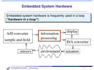
von Neumann architecture • Memory holds data, instructions. • Central processing unit (CPU) fetches instructions from memory. • Separate CPU and memory distinguishes programmable computer. • CPU registers help out: program counter (PC), instruction register (IR), general-purpose registers, etc.
CPU + memory memory address CPU PC 200 data ADD r5,r1,r3 ADD r5,r1,r3 IR 200
Harvard architecture address CPU data memory PC data address program memory data
von Neumann vs. Harvard • Harvard can’t use self-modifying code. • Harvard allows two simultaneous memory fetches. • Most DSPs use Harvard architecture for streaming data: • greater memory bandwidth; • more predictable bandwidth.
RISC vs. CISC • Complex instruction set computer (CISC): • many addressing modes; • many operations. • Reduced instruction set computer (RISC): • load/store; • pipelinable instructions.
Instruction set characteristics • Fixed vs. variable length. • Addressing modes. • Number of operands. • Types of operands.
Programming model • Programming model: registers visible to the programmer. • Some registers are not visible (IR).
Multiple implementations • Successful architectures have several implementations: • varying clock speeds; • different bus widths; • different cache sizes; • etc.
ARM Architecture Advanced RISC Machines(1990) (ACORN and Apple Computer)
ARM Architecture • ARM versions. • ARM assembly language. • ARM programming model.
ARM versions • ARM architecture has been extended over several versions. • We will concentrate on ARMv5
ARMv6 Improvement • Memory management • Multiprocessing • Multimedia support: SIMD capability
Introduction • To allow very small, yet high-performance implementations • RISC • Large uniform register file • Load/store architecture • Simple addressing modes • Uniform and fixed-length instr fields • Auto-increment and auto-decrement addr modes • Conditional execution of all instrcutions
ARM assembly language • Fairly standard assembly language: LDR r0,[r8] ; a comment label ADD r4,r0,r1
ARM data types • Byte : • Halfword : 16 bits • Must be aligned to two-byte boundaries • Word : 32 bits • Must be aligned to four-byte boundaries • ARM addresses canbe 32 bits long. • Address refers to byte. • Address 4 starts at byte 4. • Can be configured at power-up as either little- or bit-endian mode.
Processor modes • User: usr – Normal program execution modes • FIQ: fiq – Supports a high-speed data transfer or channel process • IRQ: irq – Used for general-purpose interrupt handling • Supervisor: svc – A protected mode for OS • Abort: abt – Implements VM and/or memory protection • Undefined: und – Supports software emulation of HW coprocessors • System: sys – Runs privileged OS tasks • fiq, irq, svc, abt, und – exception modes
N Z C V Registers r0 r8 r1 r9 0 31 r2 r10 CPSR r3 r11 r4 r12 r5 r13 r6 r14 r7 r15 (PC) Link register unbanked registers banked registers
Endianness • Relationship between bit and byte/word ordering defines endianness: bit 31 bit 0 bit 0 bit 31 byte 3 byte 2 byte 1 byte 0 byte 0 byte 1 byte 2 byte 3 little-endian big-endian
ARM status bits • Every arithmetic, logical, or shifting operation may set CPSR (current program statues register) bits: • N (negative), Z (zero), C (carry), V (overflow). • Examples: • -1 + 1 = 0: NZCV = 0110. • 231-1+1 = -231: NZCV = 0101.
ARM data processing – operand addressing • Instruction syntax • <opcode>{<cond>}{S} <Rd>, <Rn>, <shifter-operand> • <shifter-operand> has 11 options
Condition field • Almost all ARM instrs. – conditionally executed
31 31 28 28 25 25 21 21 19 19 16 16 12 12 7 7 5 5 4 4 3 3 0 0 cond cond 000 000 opcode opcode S S Rn Rn Rd Rd shift amount shift shift 0 1 Rm Rm Rs 0 31 28 25 21 19 16 12 7 5 4 3 0 cond 001 opcode S Rn Rd rotate immediate-8 ARM data processing – operand addressing Data processing immediate shift Data processing register shift Data processing 32-bit immediate
Shifter operand • Immediate • 8-bit constant and a 4-bit rotate (0,2,4,8,…,30) • mov r0, #0 • add r9, r9,#1 • Register operand • mov r2, r0 • Shifted register operand • ASR, LSL, LSR, ROR, RRX (by one bit) • mov r2, r0, LSL#2 ; shift r0 left by 2, write to r2 (r2=r0x4) • sub r10,r9,r8, LSR #4 ; r10 = r9 - r8/16 • sov r10,r9,r8, ROR r3 ; r10 = r9 - (r8 rotated by value of r3)
AND EOR SUB : Rd:= Rn - shifter operand RSB : Rd:= shifter operand - Rn ADD ADC (with carry) SBC RSC (reverse SBC) TST : update flags after Rn AND shifter operand TEQ CMP CMN: copmare negated ORR (logical OR) MOV BIC MVN (mov not) ARM data-processing
ARM data-processing • Shift, Rotate ? – shifter-operand • LSL, LSR : logical shift left/right • ASR : arithmetic shift left/right • ROR : rotate right • RRX : rotate right extended with C
Data operation varieties • Logical shift: • fills with zeroes. • Arithmetic shift: • fills with sign extension • RRX performs 33-bit rotate, including C bit from CPSR above sign bit.
Load and Store instructions • Two types • 32-bit word or an 8-bit unsigned byte • Load and store halfword and load signed byte • Addressing modes • Base register • Any one of GPR (including the PC) • Offset • Three format
Addressing modes • Offset • Immediate: unsigned number (12 bits or 8 bits) • Register: GPR (not the PC) • Scaled register: shifted by an immediate value • LSL, LSR, ASR, ROR, RRX • Three ways to form the memory address • EA := Base register + or – Offset • Offset • Pre-indexed • Post-indexed
Addressing modes • Base-plus-offset addressing: LDR r0,[r1,#16] • Loads from location r1+16 • Pre-indexing increments base register: LDR r0,[r1,#16]! • Post-indexing fetches, then does offset: LDR r0,[r1],#16 • Loads r0 from r1, then adds 16 to r1.
LDR LDRB LDRH LDRSB (signed byte) LDRSH (signed halfw) STR STRB STRH Load and store
Examples LDR R1, [R0] ; load R1 from the address in R0 LDR R8, [R3, #4] ; EA = [R3] + 4 LDR R8, [R3, #-4] ; EA = [R3] – 4 STRB R10, [R7, -R4] ; EA = [R7] – [R4] LDR R11, [R3, R5, LSL#2] ; EA = [R3] + ([R5]x4) LDR R3, [R9], #4 ; EA = [R9], R9 = [R9] +4 post-indexed LDR R1, [R0, #2] ! ; EA = [R0]+2, R0=[R0]+2 pre-indexed LDR R0, [PC, #40] ; load R0 from PC+0x40 (= address of the ; instruction +8 + 0x40)
Load and store multiple • Addressing modes • IA : increment after • IB : increment before • DA: decrement after • DB: decrement before
Load and store multiple • LDM • STM • Examples • LDMIA r0, {r5 – r8} ; load multiple r5-r8 from ; the address in r0 • STMDA r1!, {r2, r5, r7 – r9, r11} ; update r1
Branch instructions • Conditional branch forwards or backwards up to 32 MB • Sign-extending the 24-bit imm_data to 32 bits • Shifting the result left two bits • Adding this to the PC (the addr of branch +8) • Approximately ± 32MB • B, BL
Examples B label BCC label ; branch if carry flag is clear BEQ label ; if zero flag is set MOV PC, #0 ; branch to location zero BL func ; subroutine call MOV PC,LR ; return MOV LR, PC LDR PC, =func ;
ARM ADR pseudo-op • Cannot refer to an address directly in an instruction. • Generate value by performing arithmetic on PC. • ADR pseudo-op generates instruction required to calculate address: ADR r1,FOO
Examples start MOV r0, #10 ADR r4, start; => SUB r4,pc,#0xc start = pc - 4 - 8 = pc - 12 = pc - 0xc