Download
1 / 48
480 likes | 489 Vues
Resources. Icons represent resources Dynamic resources must be assigned a path network Resources position at nodes, not locations “Specs” field defines path, nodes, motion and rules. Resource edit table. Resources. Resource selection. Resource Specifications assign

E N D
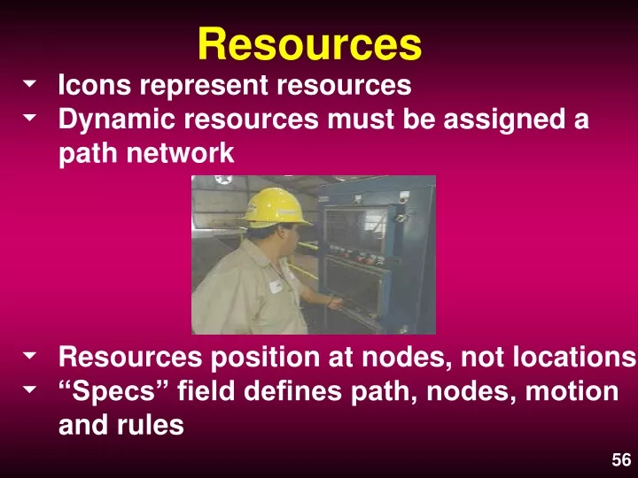
Resources • Icons represent resources • Dynamic resources must be assigned a path network • Resources position at nodes, not locations • “Specs” field defines path, nodes, motion and rules
Resource edit table Resources Resource selection
Resource Specifications assign the path network, motion, node and rules information
Resource Points let the resource occupy a position away from the node
Resources Now, along with the instructor, enter the two Resources for the “Shop Floor” model Transporter Operator
Processing What Am I ? Where Am I ? What Happens ? Now What Am I ? Where Do I Go ? Under What Circumstances ? How Do I Get There ?
Processing • Defines what entity at what location has what happening to it. • Select entity to be addressed in the Tools window. • Click on the initial entry location, then the first destination. Do remaining locations the same way. • Address individual Operation Logic and Move Logic entries as required
Select “Entity” to begin process definition
1. Click on “Part_Storage” icon to begin process definition 2. Move arrow to first destination and click to record initial movement
Entity Output Change • If an Entity changes form its Output name may change • Select the new entity name from the pull down window in the output field
Raw_Part enters the Lathe Finish_Part leaves the Lathe
Routing Rules Establish the condition for selecting the next location • FIRST Available- Go to the first listed location with available capacity • Quantity Field - Shows the number of entities that will go to the destination
This is the Quantity indicator Select the desired Routing Rule
Output Quantity • Create an Output Quantity of X in the quantity field of the routing dialogue box
Operation Logic • Operation Logic describes what happens to an entity at its current location • Operation Logic uses a series of statements or code to cause ProModel to do what you want • The Logic Builder can help you write these statements correctly
Operation Statements Cause an entity to do some action or activity • WAIT or ^ or TIME Causes an entity to wait at a location for a specified time Syntax: WAIT <time period>
Operation Statements • GET Causes an entity to request the use of a resource Syntax: GET<resource name> • FREE Causes an entity to release a previously captured resource Syntax: FREE<resource name>
Operation Statements • Usual Syntax of Get/Free Statements Get Operator Wait N(5,2) Free Operator • USE Causes an entity to request a resource for a specified time and then release the resource Syntax: USE <resource name> for <time expression>
Operation Statements • GRAPHIC <#> Causes an entity to change to a different graphic Syntax: GRAPHIC <numeric expression> • ACCUM Accumulates, without consolidating, a specified quantity of entities at a location Syntax: ACCUM <numeric expression>
Logic Builder • A way to enter logic or the names of defined items • Works from any field that accepts logic or expressions • An easy way to ensure the syntax is correct
Use the “Logic Builder” to create process logic or when you are unsure of the syntax.
Gives a short explanation Buttons change with selected statement Other options are
2. Click on Time, Keypad or Build Expression or enter a time 1. Select a statement such as WAIT
When the expression or logic is completely built, click on Paste to place the logic in the window from which the Logic Builder was selected. Then you may Close the Logic Builder or keep it open for the next statement.
Move Logic • Activated from the Routing - Move Logic field • Specifies Path Network, Time or Resource to make the move • May apply logic before and after the actual move
Click on Move Logic to bring up the window Click on Build button or use right mouse button to bring up the Logic Builder window
Basic category brings up standard Move statements
Select the Resource with which the Entity is to move Choose Paste and then Close when finished
Arrivals • Select the entity to arrive from the Tools window • Click on the Arrival location • Edit Quantity Each, First Time, Occurrences and Frequency as appropriate
Arrivals • First Time may have an entry or be left blank • INFinite may be used in Occurrences to create an unending stream of arrivals • Frequency may be a constant, a macro, a variable or a distribution
2. Select “arrival” location 1. Select “Entity” to arrive
The First Time button brings up scheduling options
Arrivals Now, along with the instructor, enter the arrival pattern for the “Shop Floor” model
Five Common Errors 1. No process defined at a destination 2. Missing a path network interface 3. Path network nodes not connected 4. Failure to release a resource 5. Failed arrivals due to insufficient capacity
No Process Defined This is the error message
Missing Interface This is the run time error message for a resource
Two Unconnected Nodes N3 N4 This is the break in the path This is the run time error message
Entity Exits with a Resource Job_Complete trying to Exit with Order_Tech
Failed Arrivals This is the error message, seen at the end of the simulation run
Running the Simulation 1. Select Simulation Options first. a. Check the Output Path. b. Check run time options and clock precision. c. Select Output Reporting option. 2. Then select Run or Save and Run.
Select “options” before running the simulation to set values
Define run length by calendar date or weekly time for shift use ... or define run length by hours ... or leave blank Set the number of replications
Select “Information” during run time to view in-process model status
Right Click Features 1. Layout widow - no edit table open a. Right click on a location lets you edit the location or the background b. Similarly, right click on resource, variable, etc. does the same thing c. Right click on the background lets you edit the background or most of the View menu options
Right Click Features 2. Layout window - edit table open a. Takes you to that record in the edit table b. Lets you delete the graphic or that particular record c. In Path Networks lets you add a joint or delete the segment d. In Processing lets you add a joint to the routing arrow, delete that routing or delete the entire process
Right click on the Transporter to bring up this edit option
Right click on the background brings up these options
Right click on a path segment takes you to the segment and gives you edit options