Download
1 / 32
320 likes | 510 Vues
Automatic Wake-Up Experience. Group 40 William Bendix, Jake Metz, & Durreh Tabassu ECE 445 Senior Design April 29, 2010. Introduction. The Automatic Wake-Up Routine provides an automated approach to the daily, morning tasks taking them out of the hands of the end user

E N D
Automatic Wake-Up Experience Group 40 William Bendix, Jake Metz, & Durreh Tabassu ECE 445 Senior Design April 29, 2010
Introduction • The Automatic Wake-Up Routine provides an automated approach to the daily, morning tasks taking them out of the hands of the end user • Seeks to reduce stress caused by morning chores and create a more pleasant environment to wake up in
Original Concept Blinds Coffee Maker Alarm Internet Thermostat
Overview • System controlled by “base-station” alarm clock • Based around a modular design • Utilizes RF wireless to allow communications between the base-station and different modules
Modular Design • Central base station provides normal alarm clock functions • Coffee maker module to operate coffee machine prior to wake up time • Thermostat control to create a comfortable temperature • Blinds control to wake end user up with natural light • Vocal announcements to rouse end user
Automatic Coffee Maker • Allows for wireless control of Coffee maker • Could be attached to any model of Coffee maker • Small, plastic housing for aesthetic placement on kitchen counter
Automatic Coffee Maker • Relay connected to power line of coffee maker • Only receives wireless signal when Coffee maker switch set to “on” • Powered from DC wall-adapter or 4 AA batteries
Alarm Clock 7 segment displays BCD to Seven segment converters
Project build- Alarm clock • Coding PIC Microcontroller • Use MPLab and CCS compiler • Program with PICStart • Build Device on Breadboard • Testing • Debugging • Design on Eagle for PCB Fabrication • a. More Debugging
Challenges • Getting PIC to output constant high/low values • I2C Communication • PCB fabrication – shorts and opens
Schematic for the thermostat Schematic for the Blinds Circuit
PWM signal for the motor Duty cycle changing between 30%-100% Frequency : 125kHz Period: 8.0 us.
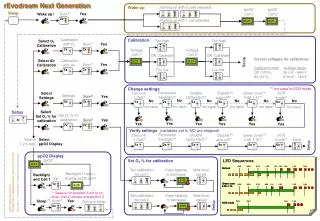
Testing procedures Thermostat: • Set the desired temperature with local inputs to PIC • 2) Test the high and low temperature trigger for the sensor using a blow dryer. • 3) Test the temperature setting through the wireless connection • 4) Test the heater is on using an LED.
Blinds Circuit: 1) Test the motor control by manually running the motor without the PIC by using a function generator. 2) Test the wireless control of motors by sending signal to PIC 3) Battery capacity check a. Use a multimeter to test battery voltage levels b. Run the motor for 5 minutes (corresponding to 2 motor runs per day at 5 sec/run for 30 days) c. Check the Battery voltage level again
Longevity of Power Supply The thermostat and the blinds circuit would be powered separately using 4AA batteries. Considering the motor to run for 5seconds a day, its power consumption is summarized in the table below. Average capacity of 4AA batteries = 2.4VAh Even after considering the negligible power consumed by the thermostat and the other parasitics of the circuit we can see that our battery power would easily last for a month.
Wireless Communications Transmitter: Receiver: Uses a 315 MHz signal that is Modulated using on off keying
Wireless Communications • Transmitter must attain DC-level before sending data • Receiving circuit must be able to determine which Module the base-station is talking to and what function it is meant to perform • Must not interfere with other wireless devices
Antenna: Calculations Transmission: Transmission power: Pt = 10 mW distance: r = 30 m Receiver power: Pr = -110 dBm frequency: f = 315 MHz Power per unit area: S = Pt/(4*pi*r2)= 8.84 x 10⁻⁷ Pr = 10-110/10=10-11mW Effective area: Aeff = Pr/S = 10-14/8.84 x 10-7 = 1.13 x 10⁻⁸ m2 wavelength = lambda = c/f = 3 x 10⁸/315 x 106 = .9517 m Antenna Gain: Aeff = lambda2*G/(4*pi) G = 4*pi*1.13 x 10⁻⁸/.95172 = 1.57 x 10⁻⁷ Our calculations show that the required Gain for the antenna is far below a value that a typical antenna would be expected to have
Wireless Communication • Based on RF-Link 315 MHz 2400 Baud wireless chips • Base-Station contains Transmitter • Modules each have a Receiver Transmitter Receiver
Wireless Communication • Transmission Scheme • Calibration signal to set DC-Level: $55 six times • Packet Header: $FF, $00, $FE • 8-bit MODULEID followed by INVMODULEID • 8-bit DATA followed by INVDATA • 8-bit CHECKSUM (MODULEID+DATA) followed by INVCHECKSUM • Appending characters: $AA four times • Sends entire scheme 20 times to ensure reliability
Wireless Communication • Sample HyperTerm output of transmitter • UUUUUUÿþŠu4˾AªªªªUUUUUUÿþŠu4˾AªªªªUUUUUUÿþŠu4˾AªªªªUUUUUUÿþŠu4˾AªªªªUUUUUUÿ þŠu4˾AªªªªUUUUUUÿþŠu4˾AªªªªUUUUUUÿþŠu4˾AªªªªUUUUUUÿþŠu4˾Aªªªª • Sample HyperTerm input from receiver • ªªþŠp4Ê<@ªªªªþ€t4¼@ ªªªþŠt0ʼ@ªªªªªªªªþˆu4Ê<@ªªªªþˆu4Â<@¨ªªªþˆu$¾@ ªªªþŠu4˾@ ªªªþŠt0˼@ ªªªþˆu4Ê<@€ªªªþŠt0ʼ@ ªªªþŠt ˼@ªªªªþŠp4Ê<@ªªªªþŠu4Ê<@ ªªªþ€u4¾@€ªªª þŠp0Ë<@ªªªªþŠp ʼªªªª
Voice Synthesizer • Accepts ASCII character inputs at 9600baud serial • Produces English text • Components: • TTS256 Allophone library • SpeakJet Complex Sound Synthesizer • LM386 based Audio Amp
Voice Synthesizer • PCB I/O: • Serial Data in • Power Inputs • Configuration Switches • TTS256 Status • SpeakJet “Ready” and “Speaking” signals Serial Data In TTS256 Status Out Allophone Codes “Ready” Signal SpeakJet Voice Signal Amplified Audio Signal Out LM386 Audio Amp
Voice Synthesizer • Can be used to add voice synthesis to any project • SpeakJet Complex Sound Synthesizer • Creates audible voice synthesis when provided with vocal allophones using 5-channel synth • Contains a library of built-in sound effects for future projects (R2D2 anyone?) • Inputs to reset chips and set VoiceSynth in Demo Mode or Baud Rate Configure
Scaling Back • Original project was meant to have a webserver to download GoogleCal appointments and announce audibly • Web Server was taking too long to construct and there was question as to whether a PIC would be able to utilize all of the GoogleAPI’s • Found it more useful to get wireless and modules working • All modules were originally meant to be on boards, but time constraints prevented this
Ethical Considerations • Coffee maker will only operate when user has set the on switch and requires the user to turn off after operation • Reduces the chance of overheating due to system error • Places the responsibility in the user’s hands just as with a normal Coffee Maker
Ethical Considerations • Wireless interference • 315 MHz frequency is set for commercial use. Our wireless frequency does not interfere with any commonly used frequencies like that of the cell phones.