Download
1 / 52
730 likes | 1.38k Vues
Theoretical basis for data communication. Transmission of data. Data must be transformed to electromagnetic signals to be transmitted. Data : Analog or Digital. Analog data : human voice, chirping of birds etc , converted to Analog or digital signals

E N D
Transmission of data Data must be transformed to electromagnetic signals to be transmitted.
Data : Analog or Digital • Analog data : human voice, chirping of birds etc , converted to • Analog or digital signals Digital : data stored in computer memory, converted to • Analog or digital signals
Examples • Analog data as analog signal : Human voice from our houses to the telephone exchange. • Analog data as digital signal : most of the systems today : Say Human voice, images sent on digital lines .. New telephone system (digital exchanges) • Digital data as analog signal : computer data sent over internet using analog line .. Say telephone line ( say our house to the exchange) • Digital data as digital signal : say from one digital exchange to another
Signals : Analog or digital • Analog signal has infinitely many levels of intensity (infinitely many values, continuous values) over a period of time. • Digital signal has only a limited number of defined values(discrete values) say, 0,1.
If a signal does not change at all, its frequency is zero. • If it changes instantaneously, its frequency is infinite.
An analog signal is best represented in the frequency domain.
Single-frequency sine wave isnot useful for data communication • A single sine wave can carry electric energy from one place to another. For eg., the power company sends a single sine wave with a frequency of say 60Hz to distribute electric energy to our houses.
Contd.. • If a single sine wave was used to convey conversation over the phone, we would always hear just a buzz. • If we sent one sine wave to transfer data, we would always be sending alternating 0’s and 1’s, which does not have any communication value.
Composite Signals • If we want to use sine wave for communication, we need to change one or more of its characteristics. For eg., to send 1 bit, we send a maximum amplitude, and to send 0, the minimum amplitude. • When we change one or more characteristics of a single-frequency signal, it becomes a composite signal made up of many frequenies.
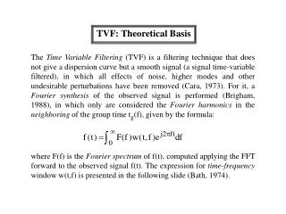
Fourier Analysis • In early 1900s, French Mathematician Jean-Baptiste Fourier showed that any composite signal can be represented as a combination of simple sine waves with different frequencies, phases and amplitudes. • More is the number of components included better is the approximation • For eg., let us consider the square wave …
Time-Voltage graph • Time on x-axis in msec, Voltage on y-axis
The first trace in the above figure is the sum of 2 sine waves with amplitudes chosen to approximate a 3 Hz square wave (time base is msec). One sine wave has a frequency of 3 Hz and the other has a frequency of 9 Hz. The second trace starts with the first but adds a 15 Hz sine wave and a 21 Hz sine wave. It is clearly a better approximation.
It can be shown (ref Kreyzsig) that this signal consists of a series of sine waves with frequencies f, 3f, 5f, 7f, … and amplitudes 4A/pi, 4A/3Pi, 4A/5Pi, 4A/7Pi,… where f is the fundamental frequency(1/T, T the time period) and A the maximum amplitude. The term with frequency f, 3f .. are called the first harmonic, 3rd harmonic,… respectively.
Frequency spectrum of a signal • The description of a signal using the frequency domain and containing all its components is called the frequency spectrum of the signal.
Composite Signal and Transmission Medium • A signal needs to pass thru a transmission medium. A transmission medium may pass some frequencies, may block few and weaken others. • This means when a composite signal, containing many frequencies, is passed thru a transmission medium, we may not receive the same signal at the other end.
Bandwidth of a channel • The range of frequencies that a medium can pass without loosing one-half of the power contained in that signal is called its bandwidth.
Representing data as Digital Signals • 1 can be encoded as a positive voltage say 5 volts, 0 as zero voltage (or negative voltage say –5 volts) • Most digital signals are aperiodic. Thus we use • Bit interval (instead of period) : time required to send one bit = 1/ bit rate. • Bit rate (instead of frequency) :number of bits per second.
Digital signal as Composite Signal • Digital signal is nothing but a composite analog signal with an infinite bandwidth. • A digital signal theoretically needs a bandwidth between 0 and infinity. The lower limit 0 is fixed. The upper limit may be compromised.
Relationship b/w bit rate and reqd. channel b/w (informal) • Imagine that our computer creates 6bps • In 1 second, the data created may be 111111, no change in the value, best case • In another, 101010, maximum change in the values, worst case • In another, 001010, change in between the above two cases • We have already shown .. More the changes higher are the frequency components
Using single harmonic – just to get the intuition • The signal 111111 (or 00000 ) can be simulated by sending a single-frequency signal with frequency 0. • The signal 101010 (010101) can be simulated by sending a single-frequency signal with frequency 3 Hz. (3 signals or sine waves per second)
All other cases are between the best and the worst cases. We can simulate other cases with a single frequency of 1 0r 2 Hz (using appropriate phase). • I.e. to simulate the digital signal at data rate 6bps, sometimes we need to send a signal of frequency 0, sometimes 1,sometimes 2 and sometimes 3. We need that our medium should be able to pass frequencies of 0-3 Hz.
Generalizing the example above • Bit rate = n bps • Best case ---- frequency 0 Hz • Worst case ----- frequency n/2 Hz • Hence B (bandwidth) = n/2
Using more harmonics • However, as said earlier, one harmonic does not approximate the digital signal nicely and more harmonics are required to approximate the digital signal. • As shown earlier, such a signal consists of odd harmonics • When we add 3rd harmonic to the worst case, we need B = n/2 + 3n/2 = 4n/2 • When we add 5th harmonic to the worst case, we need B = n/2 + 3n/2 + 5n/2= 9n/2 and so on. • In other words, B >= n/2 or n <= 2B
Relationship b/w bit rate and reqd. channel b/w (informal) • Hence we conclude that bit rate and the bandwidth of a channel are proportional to each other.
Analog vs Digital • Low-pass channel : has a bandwidth with frequencies between 0 and f (f could be anything including infinity). • Band-pass channel : has a bandwidth with frequencies between f1 (>=0) and f2 • A band-pass channel is more easily available than a low-pass channel.
Digital Rate limits • Data rate depends on 3 factors: • The bandwidth available • Number of levels of signals • Quality of the channel (noise level)
Noiseless Channel: Nyquist Bit rate • b = 2 B log L (log is to base 2) b : bit rate B : Bandwidth L : number of levels
Noisy channel : Shannon Capacity • C = B log (1 + SNR) C = capacity of the channel in bps B = Bandwidth SNR = signal to noise ratio
Digital vs Analog contd… • Digital signal needs a low-pass channel • Analog signal can use a band-pass channel. • Moreover, bandwidth of a signal can always be shifted ( a property required for FDM – The bandwidth of a medium can be divided into several band-pass channels to carry several analog transmissions at the same time.)
Example 9 Consider an extremely noisy channel in which the value of the signal-to-noise ratio is almost zero. In other words, the noise is so strong that the signal is faint. For this channel the capacity is calculated as C = B log2 (1 + SNR) = B log2 (1 + 0)= B log2 (1) = B 0 = 0
Example 10 We can calculate the theoretical highest bit rate of a regular telephone line. A telephone line normally has a bandwidth of 3000 Hz (300 Hz to 3300 Hz). The signal-to-noise ratio is usually 3162. For this channel the capacity is calculated as C = B log2 (1 + SNR) = 3000 log2 (1 + 3162) = 3000 log2 (3163) C = 3000 11.62 = 34,860 bps
Using both the limits • In practice we use both the limits to determine, given the channel bandwidth, what should be the number of levels a signal should have.