Download
1 / 36
520 likes | 1.17k Vues
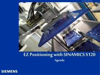
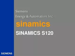
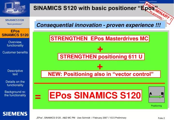
Consequential innovation - proven experience !!!. A. B. Positioning. SINAMICS S120 with basic positioner “Epos”. EPos SINAMICS S120. STRENGTHEN EPos Masterdrives MC. +. STRENGTHEN positioning 611 U. +. NEW: Positioning also in “vector control”. =. EPos SINAMICS S120.

E N D
Consequential innovation - proven experience !!! A B Positioning SINAMICS S120 with basic positioner “Epos” EPos SINAMICS S120 STRENGTHEN EPos Masterdrives MC + STRENGTHEN positioning 611 U + NEW: Positioning also in “vector control” = EPos SINAMICS S120 Folie 2
Overview of the functionality: • Absolute and relative positioning of linear and rotary axes (modulo) with motor encoder or machine encoder. • Jogging: Position-controlled traversing; endless or a specified “step width” • Referencing:- reference point approach – including reversing cam functionality- “flying referencing” – subordinate - also possible for positioning modes in operation - reference point setting- absolute encoder adjustment (when the positioning system is commissioned for the first time) • Operating mode “MDI / direct setpoint input” (based on “Masterdrives MC – Epos”): “Flying and continuous” setpoint changes (e.g. via the PLC) possible while traversing “Flying“ change between setting-up (endless closed-loop position control) and positioning possible • Operating mode “traversing blocks” (based on “611U”): 64 traversing blocks – including block change enable conditions and specific tasks;e.g.: program steps (skips), “continue flying”, waiting times, setting digital outputs;(“traverse to fixed endstop”, “external block change enable signals” and “jerk” from V2.5 onwards) • Software limit switch: Traversing range limiting by evaluating the position setpoint • “Stop cam”: The traversing range is limited by evaluating hardware limit switches • Backlash compensation • Dynamic following error monitoring, positioning/ standstill [zero speed] monitoring, 2 basic cam switching signals Overview, functionality Folie 3
Overview of the functionality: • The “basic positioner” is available in control types “servo” AND “vector” in the S120 and S150! (not in Simotion D with Sinamics Integrated) • Full graphics support (screen forms and Wizards) using StarterFrom the configuration of the mechanical system including background calculations through commissioning up to operator control and diagnostics • “All operating modes can be controlled via the PC” for diagnostics and commissioning including shared “control panel” for both closed-loop speed and position controlled operation • Pre-configured Profidrive positioning telegrams Positioning telegram types (7 , 110) (9 from V2.5 onwards) are available in SINAMICS and when selected are automatically correctly “connected-up” - this therefore guarantees fast and simple connection to automation devices. • The “basic positioner” offers flexible connection and can be adapted in the application engineering as it is predominantly equipped with BICO technology.This results a wide range of potential applications. • The “basic positioner” can be activated depending on the requirement on an axis-for- axis basis (scalable functionality)i.e. due to the fact that the “basic positioner” FUNCTION MODULE can be selected on an axis-for-axis basis, the performance of the CU320 is not utilized to the maximum when commissioning/engineering the system. • In the expert mode it is possible to only activate the sub-set “position controller/actual value conditioning” i.e. without upstream position ramp-function generator) – this allows the computation time utilization to be reducedthis allows e.g. free connection to automation systems that can/must carry-out the interpolation themselves. Overview, functionality Folie 4
Example of STARTER screen forms: “Drive Navigator”:“navigates users through the control loop” Overview, functionality Configuring the MECHANICAL SYSTEM Folie 5
Example of STARTER screen forms: “Control panel”: Commissioning and diagnostics via the PC control: Overview, functionality MDI, e.g.:Setpoints via the PLC Folie 6
Customer benefits SINAMICS S120 with “basic positioner” • “flying” and “continuous” mode/setpoint changes while actually traversing without requiring mandatory “handshaking”, including “easy-to-use” benefits/ connection, including “process shortening” transitions without the axes coming to a standstill • Can be simply and ideally connected to a PLC (..even third-party PLCs and process data) • Can be simply adapted in the application engineering and simple to handle • Simple traversing block handling and implementation of “fixed” traversing blocks • Graphic configuration, commissioning and operator screen forms (tool incl. control panel) • “Basic positioning” is still available independent of the control technique vector / servo (..and their associated limits and constraints) • Proven experience in this application area – with ongoing innovation Customer benefits ===> cost and time saving===> an innovation jump has been made and plant/system productivity increased===> supplementary resources have been eliminated thanks to the application capability===> engineering costs have been reduced Folie 7
Descriptive text (1/2) of the functionality: The basic positioner is used to position linear and rotary axes (modulo) – in either absolute/relative terms – using a motor encoder (indirect measuring system) or an encoder mounted on the machine (direct measuring system). It is available as additive function module that can be activated in the basic control types – servo control and vector control. Further, user-friendly configuring, commissioning and diagnostic functions (graphically prompted) are available in STARTER for the basic positioning functionality.Using STARTER, a control panel is available for the basic positioner and closed-loop speed controlled operation – this can be used to control the functionality per PC for commissioning or diagnostics.When the basic positioner is activated, the closed-loop position control is also activated. This is realized automatically when activating the basic positioner via the drive Wizards of STARTER. Further, the “internal interconnections) (BICO technology) that are necessary are automatically established.Pre-configured ProfiDrive positioning telegrams are available – when they are selected, the internal “interconnection” to the basic positioner is automatically established. The closed-loop position control essentially comprises two parts: -- position actual value conditioning (including the subordinate measuring probe evaluation and reference mark search) -- position controller (including limits, adaptation, pre-control calculation) -- monitoring functions (standstill, positioning and dynamic following error monitoring, cam signals) Further - using the basic positioner - the following functions can also be executed: Mechanical system:-- backlash compensation -- modulo correction Limits:-- velocity/acceleration/deceleration limits -- software limit switch (traversing range limiting by evaluating the position setpoint) -- stop cams (the traversing range is limited by evaluating the hardware limit switch) Descriptivetext Folie 8
Descriptive text (2/2) of the functionality: Referencing and adjusting:-- setting the reference point (for axes are at standstill) -- reference point approach (dedicated operating mode including the reversing cam functionality, automatic direction of rotation reversal, referencing to “cam and encoder zero mark” or only “encoder zero mark” or “external equivalent zero mark (BERO)") -- flying referencing (during “normal" traversing motion, can be referenced, superimposed using the measuring probe evaluation; generally, evaluation of e.g. a BERO proximity switch. Superimposed function for the following operating modes “jogging”, “direct setpoint input/MDI" and “traversing blocks". -- absolute encoder adjustment Operating mode – traversing blocks (64 traversing blocks):-- the traversing blocks saved in the device are used for positioning – including block change enable (advance) conditions and specific tasks (requests) for an axis that was previously referenced -- traversing block editor using STARTER -- a traversing block contains the following information/data: Task number and task (e.g. positioning, waiting, block jump GOTO, setting binary (digital) outputs motion parameters (target position, velocity override for acceleration and deceleration) mode (e.g.: skip block, block change enable conditions such as “continue_with_stop" and “continue_flying") task parameters (e.g. delay time, block jump conditions) Operating mode – direct setpoint input (MDI):-- positioning (absolute, relative) and setting-up (endless, closed-loop position controlled) using direct setpoint inputs (e.g. via the PLC using the appropriate process data) -- the motion parameters can be continuously influenced while traversing (flying setpoint transfer) – it is also possible to make a flying change between the setting-up and positioning modes.-- the direct setpoint input mode (MDI) can also be used for non-referenced axis in the setting-up or relative positioning modes; this means that when “flying referencing” is used, flying synchronization and post-referencing (subsequent referencing) are possible. Operating mode - jogging:-- the axis is traversed in the closed-loop position controlled mode using the modes “endless position control” or “incremental jogging" (in order to traverse by one “step width" – it is possible to changeover between these modes) Descriptivetext Folie 9
Common definition : rotary axis (modulo) Descriptivetext linear axis Folie 10
Details on the functionality: • 4 OPERATING MODES(can be toggled between when an axis has reached itstarget position and is at a standstill):-JOGGING (closed-loop position controlled)-REFERENCE POINT APPROACH-MDI/DIRECT SETPOINT INPUT (positioning based on “Masterdrives MC Epos”)-TRAVERSING BLOCKS (positioning based on “611U”)Priority of the operating modes with respect to one another when they are simultaneously selected: From “top to the bottom” – i.e. JOGGING > REF. APPROACH > MDI > TRAVERSING BLOCKSIncluding subordinate (lower-level) “FLYING REFERENCING” in the operating modes “Jogging”, “Traversing blocks” and “MDI/direct setpoint input”In the operating mode “MDI/direct setpoint input” including - “flying” and it is always possible to changeover during traversing between the modes “setting-up” (= endless position-controlled traversing with v-set input) and “positioning absolute/relative”- “flying and continuous” setpoint change possible while actually traversing Details on the functionality Folie 11
Details on the functionality: • Operating mode: JOGGING The axis is traversed with position control using two modes that can be toggled between1. mode: Endless closed-loop position controlled using v-set input (the sign is evaluated)2. mode: Incremental jogging ( = in order to traverse through the specified “step width”)... two selectable setpoints are available in both modes (jogging 1 / 2) Details on thefunctionality Folie 12
Example of STARTER screen forms: Jogging: Details on thefunctionality Folie 13
Details on the functionality: • Operating mode: REFERENCE POINT APPROACH (“active referencing”)The reference point is fully automatically searched for and acquired when using an incremental measuring system (e.g. encoder)Reference point approach with the following evaluation possibilities:- “cam and encoder zero mark”, “encoder zero mark” “external equivalent zero mark (Bero)”- “set reference point” without traversing possibleReversing cam functionality Automatic direction of rotation reversal and search along the complete traversing range, the start direction can be specifiedVarious approach velocities can be specified (“to the cam”, “to the reference mark”, “to the reference point”) -e.g. to increase the accuracy of the reference mark detectionMonitoring using maximum traversing distances/tolerance bandwidths that can be specified – e.g. to the cams, between the cams and zero mark, distance to the zero markAutomatic traversing for “reference point offset possible” regarding reference mark and via reference point coordinates that can be entered via BICO Automatic direction of rotation reversal at the reference cam - so that, for example, reversing cams or hardware limit switches (when the STOP cam functionality is disabled) can be used as reference cams (this eliminates some of the hardware required)(in the START direction that can be specified the zero mark has priority as reference mark BEFORE the reference cam) Details on thefunctionality Folie 14
Example of STARTER screen forms: Reference point approach ( = “active referencing”) : Details on thefunctionality Folie 15
Details on the functionality: • Operating mode: TRAVERSING BLOCKS (positioning based on “611U” functionality)Positioning using traversing blocks saved in the device (for a referenced axis)64 traversing blocks are possible – including block change enable conditions and specific tasksUser-friendly traversing block editorFor each block, e.g. position and velocity can be separately set and the acceleration as well as the deceleration override can be enteredTasks; e.g.:“positioning absolute / relative”, “ABS_POS/_NEG” (forced direction of rotation input for modulo axes), “endless pos / neg”, “wait” (waiting time), “GOTO” (block jump), “SET_O / RESET_O” (setting / resetting from up to two digital outputs simultaneously)From V2.5 onwards: “traversing to fixed endstop” (torque limiting, endstop detection via following errror detection or external signal, detection of fixed endstop fracture and fault reaction) , “jerk” (activate, deactivate) Block change conditions:“End” , “continue with stop”, “continue flying” (at the start of braking)From V2.5 onwards: “continue external”, “continue external wait”, “continue external alarm”(External block transition via fast measuring probes or selectable BICO-signal)Traversing blocks can be “skipped” (“suppressed”)When any given traversing block is activated (BICO) a traversing block being executed can be interrupted and a flying change made into the new traversing block ! Details on thefunctionality Folie 16
Example of STARTER screen forms: Traversing block editor: Details on thefunctionality Folie 17
Details on the functionality: • Operating mode: MDI / direct setpoint input (positioning based on “MASTERDRIVES MC” EPos functionality)Positioning/setting-up with direct setpoint inputs (e.g. process data, PLC)that can also be continuously influenced even while actually traversing“Flying and continuous” setpoint transfer is possible while the axis is actually moving...e.g. setpoint data from the communications interface, PLC(e.g.: position, V-set, V-override, acceleration, deceleration, signal to forcibly change the direction of rotation) It is possible to make a “flying” change between the various modes while the axis is actually moving: - mode: Setting-up ( endless closed-loop position controlled mode, v-set input) - mode: Positioning, absolute/relative (for modulo, also: forced direction of rotation change, shortest path/distance)In this mode it is also possible to traverse a “non-referenced” axis(modes: setting-up + positioning relative), e.g. by using “flying synchronizing/referencing”This is the reason that this functionality offers, for example, the following:In the mode “MDI/direct setpoint input” in the “setting-up” mode with secondary/subordinate “flying referencing” the axis is automatically moved and referenced in the production direction during the continuous traversing motion. Thesystem can then make a “flying” change into the “positioning” mode without the axis coming to a standstill; new setpoints - e.g. via the PLC – can always be transferred.This can offer advantages for the following situations e.g. for- axes, that may only be operated in one direction of rotation or continuous material webs - minimizing the “approach time”, “waste” as well as increasing the production rate- machines with slip can also be “post-referenced” on the fly Details on thefunctionality Folie 18
Example of STARTER screen forms: Direct setpoint input / MDI : Details on thefunctionality Folie 19
Details on the functionality: • Flying referencing (“passive referencing”)Referencing the axis during “normal” traversing motionusing a “measuring probe” (standard setting)including possible continuous “post-referencing” !!!Can be executed as subordinate function in the following operating modes: “jogging”, “traversing blocks” and “MDI/direct setpoint input” !!!Can be selected for both incremental and absolute measuring systems (encoders)It is possible to toggle between measuring probes (2 measuring probe inputs can be selected, positive/negative edge) – switched over using BICO technologyFor “flying referencing” while carrying-out RELATIVE positioning it can be selected as to whether the correction value for the traversing distance should be taken into account or not For “post-referencing” it is possible to evaluate a “real/incorrect” BERO signal (inner/outer position difference “window”) Details on thefunctionality Folie 20
Example of STARTER screen forms: Flying referencing (= “passive referencing”) : Details on thefunctionality Folie 21
Details on the functionality: • Software limit switches for linear axes: For a referenced axis the traversing range is limited by evaluating the position setpoint • “Stop cams”: The traversing range is limited by evaluating a hardware limit switchThe limit switches can also be used as reversing cams or reference cams for the reference point approach – e.g. for a reference point approach the stop cam functionality is de-selected (BI:p2568) > reduces the level of hardware resources required • Velocity override can be used in all operating modes(for reference point approach “only” for reference cam approach velocity) • Backlash compensationCorrects the position actual value as a result of any mechanical play (backlash) between the motor and load • “Intermediate stop” and “reject traversing task” can be controlled in the positioning modes (“traversing blocks” and “MDI/direct setpoint input”)The “old” traversing direction can be continued after an “intermediate stop” • Dynamic following error monitoring(this eliminates velocity-dependent components and therefore permits monitoring functions to be implemented with a far more rigid tolerance – equivalent time constants of the control loop subordinate (secondary) to the position controller are taken into account),position monitoring (“target position reached”), standstill monitoring • 2 “basic” cam switching signals (in the closed-loop position control)No hysteresis, cam position can “only” be parameterized (no BICO), only ONE position for signal change for each cam (..this means no ON/OFF position for each cam), but one BICO output is available for each cam Details on thefunctionality Folie 22
Example of STARTER screen forms: “Positioning/standstill monitoring” Details on thefunctionality “Following error monitoring” Folie 23
Example of STARTER screen forms: Software limit switches and stop cams (hardware limit switch): Details on thefunctionality Folie 24
Details on the functionality: • Referencing types that are available:> Reference point approach (“active referencing”) (operating mode: see details in previous overheads)> Flying referencing (“passive referencing”) (see details in previous overheads)> Reference point setting“Reference point setting” is possible in the initial state (= target position reached and axis stationary (zero speed)), none of the operating modes are active)and from V2.5 onwards also in “intermediate stop” (“MDI” and “Traversing blocks”) > Absolute encoder adjustment(when commissioning for the first time: Determining the offset at standstill [zero speed] using the reference coordinates)The following functions are not possible for a NON-referenced axis:- “traversing blocks” operating mode- in the operating mode “MDI/direct setpoint input” the “Absolute positioning” (i.e. setting-up and relative positioning are also possible here - and are often practical!) • Changing-over between units - mm, inch, Degrees, LU– including selectable resolutions of between 1 and 0.00001 (in V2.4 and V2.5, only LU was possible) • The units LU permit the “most accurate” and the most flexible adaptation of the position actual value resolution; this is because the internal high-resolution position actual value resolution – precise to one increment – can also be used “externally” (customer perspective, setpoint input), and customers are able to select “any” setpoint normalization/actual value normalization. Details on thefunctionality Folie 25
Details on the functionality: • From V2.5 onwards:Jerk limiting (“jerk”) can be permanently activated or via PZD (BICO) in ALL operating modes.In the “traversing blocks” mode, this can be additionally activated/de-activated as a function of the particular task, if the jerk is not permanently or via PZD (BICO) activated.In V2.4, the position setpoint filter (p2533) can be used in the position controller for “rounding-off”. This is also easily possible as the position setpoint filter influences both the position setpoint as well as also the speed pre-control (assuming the symmetrical adaptation of the setpoints) and a filter that can be separately set (p2535/p2536) is available for the pre-control symmetrization (delay, position setpoint at the position controller as a ratio to the speed pre-control, “following error compensation”). • EPos is implemented as function module (computation time is only utilized when the functionis actually selected).The necessary interconnections to the “basic system” are AUTOMATICALLY established. (BICO technology interconnections are automatically established and parameterized when the function module is selected). Further, these “interconnections” – both to the basic system as well as within the EPos – can be adapted using Bico technology as part of the application engineering to implement the customer’s specific requirements; this therefore results in a wide range of possible applications. • In the expert mode, it is possible to only activate the sub-set “position controller/ actual value preparation” (i.e. without the upstream position ramp-function generator) to reduce the load on the computation time.This allows, e.g. free link to the automation systems that handle the interpolation and the position ramp-function generator channel.Further, this means that the “complex” handshaking technique, executed via the control, can be eliminated e.g. when initiating/retrieving position measured values per measuring probe (I.e.: Gn_XIST1, Gn_XIST2, Gn_STW, Gn_ZSW),this is because the “position actual value conditioning” module to a large extent automatically executes this. Details on thefunctionality Folie 26
Details on the functionality: • Position controller: PI controller algorithm is also possible (and not only P controller), in order to position, for example, large flywheel masses. Extremely large control loop time constants when compared to the sum of the small time constants are handled using position controller=PI controller /n controller=P controller.Kv can be adapted using BICO technology (PZD input) and position controller output limiting, controlled using BICO technology for e.g. moments of inertia that change, or influence during the traversing profile or approach behavior (presses, partial cross-cutter functionality), or simplified starting behavior when connecting to a third-party PLC etc. • Speed pre-control as well as torque pre-control available from the closed-loop position control. • Position actual value inversion is included in the basic device functionality. From V2.4 onwards, in addition, the direction of rotation bit is included in the basic device functionality(feedback and manipulated variables are inverted together, e.g. drive mounting RIGHT/LEFT at the machine but only one production direction). Details on thefunctionality Folie 27
Example of STARTER screen forms: “Position controller” screen form: Details on thefunctionality Folie 28
Background regarding the functionality: • Encoder systems / position actual value conditioning in conjunction with EPos:Rotary and linear encodersAll of the encoder systems (p0400) released for the basic device functionality are supported with the exception measuring systems with distance-coded zero marks.The evaluation of an indirect linear measuring system being used (motor linear encoder) as direct measuring system (encoder connected to the machine) is not supported using Starter screen forms – but is possible using the expert mode (parameter list).Rotary axis functionality (modulo) or linear axis functionalitycan be FREELY ASSIGNED both for rotary as well as also for linear motor encoders (indirect measuring system) or machine encoders (direct measuring system).Therefore, also: Rotary encoders (either mounted at the machine or motor) can be consciously operated with “linear axis functionality”Absolute encoders are supported.- Absolute value adjustment at standstill (first commissioning).Recommendation for rotary absolut encoder e.g. for linear axes:Choose the traversing range and absolut value adjustment in +/- half of the multi-turn range (Xist2).With it one “electrical overflow of the encoder because of mechanical mounting” within EXACT ONE (..not several) complete multi-turn range is in control of software (...even without “position tracking for absolut encoders”) - “Flying referencing” possible (exception).Drive data set changeover (DDS) including encoder data set (EDS, 3 encoder data sets)Presently, the position actual value conditioning for EPos can evaluate one encoder at the same time (each encoder data set) – and more is also not practical for the “Epos” functionality. However it is still planned to be able to evaluate two additional encoders at the same time through the position actual value conditioning for the EPos; e.g. for “monitoring purposes” or to “transfer to the PLC”(..as an alternative to Gn_Xist1/Gn_Xist2, etc.). Background re: the functionality Folie 29
Background regarding the functionality: • Explanation of system terminology that is necessary for a better understanding (from V2.4):“Measuring gearbox” means: (functionality in the basic device, encoder data set EDS) Ratio between the motor – motor encoder or load – machine encoder“Load gearbox” means: (functionality of the position actual value conditioning/EPos) Ratio between the load - motorThe measuring gearbox between the motor – motor encoder also influences the commutation angle (closed-loop current control) and must thus correspond to the real relationships – and for example - cannot be used to adapt to the axis cycle (product cycle, position control loop). In this case a load gearbox should be used!If a measuring gearbox is used between the load and encoder mounted on the machine then it goes without saying that an adaptation can be made to the axis cycle (product cycle).The following is implemented from V2.4 onwards:- measuring gearbox (motor – motor encoder, load – encoder mounted at the machine) and load gearbox for rotary axes/modulo or linear axis Background re: the functionality Folie 30
Background regarding the functionality: • Position tracking for absolute encodersPosition tracking is only necessary for absolute encoders and under the follow. conditions:- overflow of the multi-turn range AND multi-turn count / “gearbox" is NOT AN INTEGER NUMBERor- extension of the measuring range beyond the multi-turn range for linear axesPosition tracking from V2.4 onwards:- “only” when a measuring gearbox is used between the motor and motor encoder or load and encoder mounted on the machine for rotary axis/modulo(e.g. : 1FW3 torque motors with absolute encoder – “non integer number for the toothed belt ratio”) Additional Position tracking from V2.5 onwards (..essentially the completion):- for measuring gearboxes between the motor and motor encoder for linear axis- for measuring gearboxes between the load and encoder mounted to the machine for linear axis- for load gearboxes (motor – load) for rotary axis/modulo and linear axis Example: Gearbox ratio 1:3, the absolute encoder can count 8 revolutions Background re: the functionality Folie 31
Background regarding the functionality: Functional expansions of V2.5 in detail (part 1/5): • Traversing blocks / new task: „traversing to fixed endstop“- torque limiting- endstop detection via following errror detection or external signal- detection of fixed endstop fracture and fault reaction- Starter-mak: „„Basic positioner/Program traversing blocks/Job“ Background re: the functionality Folie 32
Background regarding the functionality: Functional expansions of V2.5 in detail (part 2/5): • Traversing blocks / new block change conditions: „External block transition“- “continue external”, “continue external wait”, “continue external alarm”External block transition via fast measuring probes or selectable BICO-signal- Starter-mask: „Basic positioner/Program traversing blocks/configuration and „Basic positioner/Program traversing blocks/Advance“ Background re: the functionality Folie 33
Background regarding the functionality: Functional expansions of V2.5 in detail (part 3/5): • Additional Position tracking from V2.5 onwards (..essentially the completion)for absolut encoders- for load gearboxes (motor – load) for rotary axis/modulo and linear axis- for measuring gearboxes between the motor and motor encoder for linear axis- for measuring gearboxes between the load and encoder mounted to the machine for linear axis- Starter-mask: „Position control / Mechanics“ or „axis assistent, configuration“ (load gearboxes) Background re: the functionality Example: Gearbox ratio 1:3the absolute encoder can count 8 revolutions Hint: For „linear axis“ with rotary absolut encoder max. +/-31 overflows behind the gearbox are allowed. Folie 34
Background regarding the functionality: Functional expansions of V2.5 in detail (part 4/5): • Jerk limiting (“jerk”)- “Jerk” can be permanently activated or via process data (BICO) in ALL operating modes.- In the “traversing blocks” mode, this can be additionally activated/de-activated as a function of the particular task, if the jerk is not permanently or via process data (BICO) activated.- Starter-mask:„Basic positioner/..“ „..limits/traversing profile limitation“ and „..Program traversing blocks/Job“ Background re: the functionality Folie 35
Background regarding the functionality: Functional expansions of V2.5 in detail (part 5/5): • Profidrive Positioning telegram type 9 (... 7 and 110 from V2.4 onwards)- Starter-mask: e.g. „Communication/PROFIBUS“ or „axis wizard“ • “Reference point setting” also in “intermediate stop” (“MDI” and “Traversing blocks”)- Starter-mask: „Basic positioner/Homing“ • configuration of standstill/position monitoring- F07450 (standstill monitoring) and F07451 (position monitoring ) correspond to F07452 (following error monitoring) are configurable from F (fault) to A (alarm).E.g. thereby it makes possible a selective tolerance via PLC (BICO) in case of further on activated monitoring. • Reversing cam functionality also with „reference point approach“ without cam mark...means even in mode „only“ “encoder zero mark” or “external equivalent zero mark (Bero)” - Starter-mask: „Basic positioner/Homing“ Background re: the functionality Folie 36
Thank you very much for your attention ! joy of use EPosBasic positioner EPos ...the chromic railat the Sinamics !!! Folie 37