Download
1 / 70
900 likes | 1.26k Vues
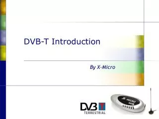
Technology Briefing DVB-T. Overview. Comparison between DVB-T and ATV COFDM implementation for DVB-T Transmitter Technology Hierarchical Modulation SFN DVB-H Off-air reception (Re-transmitters, Repeater). Digital Video Broadcasting - Terrestrial (DVB-T).

E N D
Overview • Comparison between DVB-T and ATV • COFDM implementation for DVB-T • Transmitter Technology • Hierarchical Modulation • SFN • DVB-H • Off-air reception (Re-transmitters, Repeater)
Digital Video Broadcasting - Terrestrial (DVB-T) The DVB system is defined as a “system for digital transmission of television and data signals” In fact the system introduces innovations in • Network structure • Frequency efficiency • Elimination of distortions • Digital modulation technology • Wireless data transmission to mobile receivers DVB is a revolution in terrestrial TV broadcasting
TV Transmitter TV Transmitter TV Transmitter Video Video TV Transmitter Studio of Program Provider 2 Video Distribution Network TV Transmitter Video TV Transmitter TV Transmitter Video Video Studio of Program Provider 1 Video TV Transmitter Distribution Network Studio of Program Provider 3 Video Distribution Network Video TV Transmitter Network Structure for Analog TV Each TV program requires a separate transmitter network Notes
ModulatorAmplifier Audio/Video Encoder Audio/Video Encoder Audio/Video Encoder DVB-T Network Structure ModulatorAmplifier Transport Stream Multiplexer Telecom Network (Microwave, Fibre optics) Modulator Amplifier In a DVB-T structure several TV and radio programs can share a common transmitter network Notes
Programs per Transmission Channel DVB-T Depending on the selected data rate: One H-DTV program (high definition TV) or Up to 4 S-DTV programs (standard definition TV) or Up to 8 L-DTV programs (low definition TV) Dolby digital or AC3 Multimedia applications Analog TV One S-DTV program(standard definition TV) Dolby - stereo sound TV- text (teletext)
Excellent Reception Quality Low Reception Quality ReceptionQuality Analog TVReception quality directly depends on the field strength. With growing distance the reception quality continuously decreases as the signal gets closer to the noise floor. DVB-T Excellent quality over the whole coverage area, independent of the distance between transmitter and receiver.
The Brick Wall Effect DVB-T The transition from the covered to not covered area is very sharp. The position can slightly vary according to atmospheric (weather) changes. Reception Quality Distance between transmitter and receiver The border between the covered and not covered regions is determined by the RF carrier to noise ratio within the receiver. This is given in decibels and is referred to as the C/N specification. When the receiver C/N drops below the specified level, the receiver software blanks the picture and sound, or switches to a backup source, until the C/N again raises above the threshold. Analog TVReception quality depends on field strength. With growing distance the reception quality continuously decreases. As distance from the transmitter increases, the noise in the picture increases. This is referred to a Graceful Degradation.
Multi Path Reception Reflected signal (echoes) Signal fromadjacent Tx Directly received Signal Reflected signal (echoes) Analog TVMulti path reception causes distortions (e.g. ghost pictures) or total signal loss. DVB-TMulti path reception does not influence the DVB-T signal quality. In fact reflected signals can increase the received signal strength.
Single Frequency Networks Analog TVSince multi path reception causes distortions or total signal loss, adjacent transmitters have to be operated on different frequencies. DVB-TMulti path reception does not influence the DVB-T signal quality, therefore adjacent transmitters can be operated on the same frequency.
VSB Vision Modulator UP-Converter Video + FM Forward Error Correction (FEC) Mux Program 1 Sound Modulator Audio Bitrate after Channel Coding Program 2 Forward Error Correction (FEC) Program 3 Source Coding And Data Reduction Multiplexing Channel Coding Channel coding and Error Protection Analog TVSince Analog modulation methods are used and no redundancy has been designed into the signal, Forward Error Correction is not possible. DVB-TRedundancy has been added to digital signal, and its level is selectable, therefore, Forward Error Correction has been designed into the system.
Digitalization Data Reduction Digitalization Data Reduction Digitalization Data Reduction Digital Signal Processing Multiplexing Channel Selection Service Information (SI) Insertion Conditional Access (CA) Digital Data Stream Bitrate & Format Adaptation All input signals are combined into one digital data stream which is distributed to every Transmitter in the Network
(6) , 7 or 8 MHz signal frequency Df Digital Modulation - COFDM In the Transmitter the incoming Data Stream is modulated using COFDM - Modulation Frequency Bandwidth Coded Orthogonal Frequency Division Multiplex Each Subcarrier is modulated QPSK, 16 QAM or 64QAM COFDM Signal Orthogonal Sub Carrier Spacing
Q Df = 1 / Ts Ts ... Symbol duration 11 01 I 00 10 freq. QPSK / Orthogonal Carrier Spacing Constellation Diagram of a QPSK Signal as generated in the transmitter Frequency Spectrum of orthogonal spaced QPSK modulated Carriers Orthogonal carrier spacing guarantees minimum distortions caused by adjacent sub carriers. A QPSK modulated carrier can have four different phase positions, the amplitude is constant.Therefore, a QPSK modulated carrier is able to transport 2 bits.
1 1 0 0 0 1 0 1 0 1 0 1 0 1 0 0 1 1 0 1 1 0 0 1 0 1 1 0 0 0 1 0 (n-2) (n-1) (n+1) (n+2) (n) time Guard Interval Data Stream ... 0 1 1 0 0 0 1 0 1 1 0 1 1 0 0 1 0 1 0 1 0 1 0 0 1 1 0 0 0 1 0 1 ... Separationinto Symbols COFDM Modulation Guard Interval Useful Symbol Duration
Final Comparison Analog TV DVB-T • Analog Signal Transmission • No Error Protection possible • Multi path reception causes distortions • Adjacent Transmitters have to be operated on different frequencies • Reception quality strongly depending on the field strength • Designed for single program transmission only • Digital Signal Transmission • Forward Error Protection used • Multi path reception improved system performance • Designed for Single Frequency Networks • Excellent reception quality in the complete coverage area • Designed for single and multiple program transmission
Overview • Comparison between DVB-T and ATV • COFDM implementation for DVB-T • Transmitter Technology • Hierarchical Modulation • SFN • DVB-H • Off-air reception (Re-transmitters, Repeater)
6 , 7 or 8 MHz signal frequency Df Digital Modulation - COFDM COFDM is a multi carrier system using orthogonal spaced QAM modulated sub carriers Frequency Bandwidth Coded Orthogonal Frequency Division Multiplex Each Subcarrier is modulated QPSK, 16 QAM or 64QAM COFDM Signal Orthogonal Sub Carrier Spacing
COFDM Symbol (n-1) COFDM Symbol (n) COFDM Symbol (n+1) signal (n-1) (n) (n+1) t Tg Ts Total Symbol Duration COFDM in the Time Domain Useful Symbol Duration Guard Interval At the beginning of each symbol all sub carriers are modulated with a new data content then transmission begins. The modulation of each sub carrier remains unchanged during the whole useful symbol duration No signal is transmitted during the guard interval. This gives all echoes from the previous symbol time to dissipate before the next symbol is transmitted. Additional information concerning this topic is given in slides 56 and 57 Notes
Q Q Q 1000 0000 11 00 I I I 10 01 1100 0110 Sub Carrier Modulation QPSK 64-QAM 16-QAM QPSK: 4 carrier positions A QPSK carrier can transport 2 bits 16-QAM: 16 carrier positions A 16-QAM carrier can transport 4 bits 64-QAM: 64 carrier positions A 64-QAM carrier can transport 6 bits
1 1 0 0 0 1 0 1 0 1 0 1 0 1 0 0 1 1 0 1 1 0 0 1 0 1 1 0 0 0 1 0 (n-2) (n-1) (n+1) (n+2) (n) time Visualization of COFDM Modulation Data Stream ... 0 1 1 0 0 0 1 0 1 1 0 1 1 0 0 1 0 1 0 1 0 1 0 0 1 1 0 0 0 1 0 1 ... Separationinto Symbols COFDM Modulation Guard Interval Useful Symbol Duration A symbol contains one sub symbol for each sub carrier, therefore, one symbol modulates all sub carriers
u ............ 4 5 6 n-2 n-1 n 0 1 2 3 t ............ ............ u ............ 4 5 6 n-2 n-1 n 0 1 2 3 t ............ f OFDM Modulation Position of sub symbols in the incoming bit stream Position of sub symbols assigned to the sub carriers in the OFDM signal is the same as their position in the incoming data stream If several adjacent sub carriers are attenuated, as could happen with multipath or other types of interference, much adjacent data will be corrupted. This type of error is difficult for the forward error correction circuits to correct. Notes
u ............ 4 5 6 n-2 n-1 n 0 1 2 3 t ............ u ............ n 3 1 6 4 n-2 2 n-1 5 0 t ............ COFDM Modulation Position of sub symbols in the incoming bit stream Position of sub symbols assigned to the sub carriers in the COFDM signal is not the same as their position in the incoming data stream If several adjacent sub carriers are attenuated, because of multipath or other types of interference, the corrupted data will be interleaved throughout the data stream when the incoming data stream order is re-established in the receiver. This type of error is easier for the forward error correction circuits to correct. Notes
Selection of transmission parameters for 8 MHz Channel Bandwidth DVB-T Modes The wide selection of transmission parameters allows adaption of DVB-T to the individual requirements of a broadcaster Distance between SFN transmitters or between direct and multipath signals is determined by: D = Guard Interval x Vo Vo = velocity of light in free space
Useful Bit Rates for DVB-T The useful bit rate, in Mbps, is dependant on the sub carrier modulation, the code rate, and the guard interval size The highest useful bit rate provides the lowest C/N The lowest useful bit rate provides the highest C/N
Q Q I I QPSK - Sub Carrier Modulation Inaccuracy caused by noise added in the transmission channel Maximum allowed inaccuracy for Error free reception Constellation Diagram of a QPSK signal as generated in the transmitter Constellation Diagram of a QPSK Signal as received by a receiver
Q Q I I 16-QAM - Sub Carrier Modulation Inaccuracy caused by noise added in the transmission channel Maximum allowed inaccuracy for Error free reception Constellation Diagram of a 16-QAM signal as generated in the transmitter Constellation Diagram of a 16-QAM Signal as received by a receiver
Q Q I I 64-QAM - Sub Carrier Modulation Inaccuracy caused by noise added in the transmission channel Maximum allowed inaccuracy for Error free reception Constellation Diagram of a 64-QAM signal as generated in the transmitter Constellation Diagram of a 64-QAM Signal as received by a receiver
Minimum Required C/N Required C/N ratio for non hierarchical modulation and 8 MHz channel bandwith: • Gaussian Channel • directional antenna used • direct reception • Ricean Channel • directional antenna used • multi path reception • Rayleigh Channel • non-directional antenna • multi path reception
Convolutional (Inner) Coder • Code Rate refers to the Convolutional Coder • This is part of the forward error correction which is the Inner Coding • Redundant (forward correction) bits are added to the data stream • This coding is specified as a fraction • For example, a code rate of ½ means that for every data bit entering the coder one redundant bit is added • One bit goes into the coder and two bits leave • A code rate of 2/3 means that two data bits enter the coder and three bits leave the coder • A code rate of 7/8 means that seven data bits enter the coder and eight bits leave the coder
Convolutional (Inner) Coder • A code rate of ½ is the least data efficient but it provides the most robust forward error correction • It provides the lowest C/N ranges • C/N is the minimum carrier to noise ratio required by the receiver in order to produce an error free reception (perfect picture and sound) • A code rate of 7/8 is the most data efficient but it provides the least robust forward error correction • It gives the highest C/N ranges, depending of the other modulation specifications • To cover the same area as an equivalent ½ code rate, a much higher ERP would be required. This requires greater transmitter output power
Field strength C/N C/N C/N Distance in km Coverrage Area of DVB-T Transmitters This curve represents the RF signal to noise ratio verses distance from the transmitter sitefor a given site effective radiated power (ERP) The area covered by a DVB-T transmitter is strongly depending on transmitter site ERP and the selected parameters for the COFDM signal, see following examples 64 QAM, GI 1/16 Code rate 7/8,~ 30 Mbit /s C/N: 20.1 dB 16 QAM, GI 1/4 Code rate 3/4~ 15 Mbit/s C/N: 12.5 dB QPSK, GI 1/4 Code rate 1/2 ~ 5 Mbit/s C/N: 3.1 dB noise floor The three C/N values given above are represent Gaussian channel values
Summary of Useful Bit Rates Vs Code Rates The chart below provides a convenient comparison of the effects of Modulation Type, Guard Interval, and Code Rate on Useful BIt Rate and required C/N
24,88 Mbit/s Bitrate Number of Programs per DVB-T Channel Example for DVB-T using 64 - QAM, Code rate 3/4, Guard interval 1/8 HDTV EDTV EDTV EDTV SDTV SDTV SDTV SDTV LDTV LDTV LDTV LDTV LDTV LDTV LDTV LDTV SDTV Standard Definition TV 3 ... 6 Mbit/s EDTV Extended Definition TV 6 ... 8 Mbit/s LDTV Low Definition TV 1.5 ... 3.0 Mbit/s HDTV High Definition TV 20 ... 30 Mbit/s
Overview • Comparison between DVB-T and ATV • COFDM implementation for DVB-T • Transmitter Technology • Hierarchical Modulation • SFN • DVB-H • Off-air reception (Re-transmitters, Repeater)
ModulatorAmplifier Transport Stream Multiplexer Telecom Network (Microwave, Fibre optics) ModulatorAmplifier Audio/Video Encoder Audio/Video Encoder Audio/Video Encoder Modulator Amplifier DVB-T Network Structure
ASI - Signal(MPEG2-TS) RF - Signal (COFDM) I/Q - Signal IF - Signal (COFDM) Signal Definition IQ Modulator Up-converter Power Amplifier COFDM - Encoder ASI ... Asynchronous Serial Interface I/Q ... In-phase / Quadrature COFDM ... Coded Orthogonal Frequency Division Multiplex
COFDM- Encoder I/Q Modulator I-Signal COFDM- Encoder ASI - Signal Q-Signal 90° IF COFDM Encoder / COFDM Modulator Digital or Analog I/Q Modulator COFDM - Signal IF
Overview • Comparison between DVB-T and ATV • COFDM implementation for DVB-T • Transmitter Technology • Hierarchical Modulation • SFN • DVB-H • Off-air reception (Re-transmitters, Repeater)
What is Hierarchical Modulation ? • Hierarchical modulation allows two digital data streams to be broadcast simultaneously by one transmitter • The LP Stream (Low Priority) • Higher bit rate • Less robust (higher C/N needed) • High quality signal which reaches a shorter distance • The HP Stream (High Priority) • lower bit rate • more robust (less C/N needed) • Lower quality signal which reaches a greater distance • The code rate can be selected individually for each channel
Q Hierarchical ModulationQPSK in 16-QAM Q High priority bit stream (HP) defines active quadrant(left two numbers in each symbol) 10 00 Q I 1000 1010 0010 0000 01 11 1001 1011 0011 0001 I 1101 1111 0111 1101 10 00 1100 1110 0110 0100 I Low priority bit stream (LP) defines position in the active (high priority) quadrant (right two numbers in each symbol). Notice that the four LP quadrants form mirrors of each other. 01 11
Q High priority bit stream (HP) defines active quadrant Q I Q I Low priority bit stream (LP) defines position in active(high priority) quadrant Hierarchical ModulationQPSK in 16-QAM The sum of the high and low priority (dashed) vectors produces the resultant (solid) vector This vector indicates the active HP symbol This vector indicates the active LP symbol I Note: The entire low priority constellation appears in the active (high priority) quadrant
Q High priority bit stream (HP) defines active quadrant Q I I Low priority bit stream (LP) defines position within theactive (high priority) quadrant Hierarchical ModulationQPSK in 16-QAM This vector indicates the active HP symbol Q This vector indicates the active LP symbol The sum of the high and low priority (dashed) vectors produces the resultant (solid) vector I
Q I Q Hierarchical ModulationQPSK in 16-QAM Q This vector indicates the active HP symbol I This vector indicates the active LP symbol This is how the resultant Hierarchical Modulation constellation (and vector) appears I
Q High priority bit stream (HP) defines actual quadrant I Q Q I I Low priority bit stream (LP) defines position in actual quadrant Hierarchical ModulationQPSK in 64-QAM This vector indicates the active HP symbol This vector indicates the active LP symbol Note: The entire low priority constellation appears in the active (high priority) quadrant
Field strength C/N C/N C/N Distance in km Coverrage Area of DVB-T Transmitters This curve represents the RF signal to noise ratio verses distance for a given effective radiated power (ERP) from the transmitter site The area covered by a DVB-T transmitter is strongly depending on transmitter site ERP and the selected parameters for the COFDM signal, see following examples 64 QAM, GI 1/16 Code rate 7/8,~ 30 Mbit /s C/N: 20.1 dB 16 QAM, GI 1/4 Code rate 3/4~ 15 Mbit/s C/N: 12.5 dB QPSK, GI 1/4 Code rate 1/2 ~ 5 Mbit/s C/N: 3.1 dB noise floor The three C/N values given above are represent Gaussian channel values
Why Use Hierarchical ? • Transmit services to portable and fixed receivers • Increase net bit rate of the broadcast channel • Transmit services to stationary and mobile receivers • Transmit HDTV and SDTV at the same time with different coverage areas
Stationary vs Portable receivers Non- Hierarchical LP HP LP: 16-QAM, GI 1/8, FEC 3/4 Bit rate: 16.59 Mbps C/N (Gaussian): 18.6 dB Non-hierarchical: 64 QAM, GI 1/8, FEC 2/3 Bit rate: 22.12 Mbps C/N (Gaussian): 16.5 dB HP: QPSK, GI 1/8, FEC 3/4 Bit rate: 8.29 Mbps C/N (Gaussian): 13.7 dB Hierarchical Transmission provides an additional 2.76 Mbps transport stream bandwidth, with the HP signal covering a larger service area than the Non-Hierarchical signal
Mobile & Stationary reception RF1 Non- Hierarchical RF1 LP RF 2 Non- Hierarchical RF 1 HP Non-hierarchical RF1: 64 QAM, GI 1/8, FEC 2/3 = 22.12 Mbps C/N (Gaussian): 16.5 dB Non-hierarchical RF2: QPSK, GI 1/8, FEC 2/3 = 7.37 Mbps C/N (Gaussian): 4.9 dB LP - RF1: 16-QAM, GI 1/8, FEC 3/4 = 16.59Mbps C/N (Gaussian): 18.6 dB HP - RF1: QPSK, GI 1/8, FEC 1/2 = 5.53 Mbps C/N (Gaussian): 8.9 dB
Mobile & Stationary reception RF1 Non- Hierarchical RF1 LP RF 2 Non- Hierarchical RF 1 HP The Hierarchical RF1 covers a greater area than Non-Hierarchical RF1 and has the same transport stream bandwidth. Non-Hierarchical RF2 (in addition to Non-Hierarchical RF1) provides an additional 7.37 Mbps transport stream bandwidth, and RF2 covers a larger service area, but it requires additional equipment, greater cost, and a second RF channel.