Download
1 / 35
350 likes | 356 Vues
This MEG Review in July 2004 will address the beam line studies, including the beam spot size and the current status of each component. The collaborative effort aims to improve the beam quality and maximize transmission efficiency.

E N D
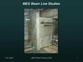
MEG Beam Line Studies E5 Z-Branch Collaborative Effort !!! MEG-Review July 2004
Topics to be Addressed • Overview • Current Component Status • Beam spot size • Summary / Conclusions • Beam Line Commissioning Schedule MEG-Review July 2004
Beam Line Overview • Beam Line Objectives • Couple ‘Z’-Branch elements in shielding to the detector i.e. COBRA • Stop maximum number of μ+ in thinnest target with minimal background contamination • No Iron allowed in vicinity COBRA→ Solenoid coupling • 28 MeV/c surface μ+ beam with high transmission efficiency→ Rate • Reject beam e+ background e+/μ+~ 10→Wien Filter • Small beam spot size at target in COBRA→ careful optics + collimator system + solenoid • Thin slanted target min. thickness for → 37 mg/cm2CH2 Tg at 22 + degrader system E5 Area MEG-Review July 2004
Beam Line Overview Contd. • Collimator system • Beam Transport Solenoid BTS • Degrader + Collimator system • Target system + He-Bag System • Triplet I • Wien Filter E^B Separator • Triplet II MEG-Review July 2004
Trip. Colli. WIEN Solenoid µ+ µ+ Triplet 2 e+ e+ Filter 1 Recap Previous Main Results P-Spectra: -Kinematic Edge (29.79 MeV/c) Theoretical func. P3.5 folded with Gaussian ΔP/P + Const. Cloud µ+ contribution Integrated Rate 4cm Tg.E @ 1800µA Nµ~1.3·108 µ+/s (2.3·108 µ+/s 6cm Tg.) Integrated Rate After Separator 4cm Tg.E @ 1800µA Nµ~9.4·107 µ+/s (1.7·108 µ+/s 6cm Tg.) Ne/Nµ > 9 Ne~ 8.7·108 e+/s Transmission Factors TSep= (71±5)% TColli= (90±5)% “Z-Branch” Pcent=(28.2±0.1)MeV/c ΔP/P =(7.9±0.6)% FWHM PBeam=(28.2±0.9)MeV/c Consistent with TURTLE & P-Slit settings/Calib. MEG-Review July 2004
Trip. Colli. WIEN Solenoid µ+ µ+ Triplet 2 e+ e+ Filter 1 Previous Main Results contd… Integrated Rate After PSC Solenoid !!! 4cm Tg.E @ 1800µA Nµ~6.1·107 µ+/s (1.1·108 µ+/s 6cm Tg.) Beam Spot: σX ~ 5.3 mm σY~ 6.5 mm Transmission Factor Solenoid TSol= 71 % Integrated Rate 4cm Tg.E @ 1800µA Nµ~8.5·107 µ+/s (1.5·108 µ+/s 6cm Tg.) µ/e Separation 11.8cm 7.2σ !!! With larger Bore i.e. BTS T>71% MEG-Review July 2004
e+ Foils CH2 at focus Solenoid µ+ CH2 Tg Fix Degrader Var. Tg Degrader & Stopping Distribution Measurements Target Thickness vs. NaI Rate Michel Range Curve using NaI: AIR VAC R ~ 870 µ CH2 Degrader Target Target 88% stopped in 400µ CH2 Tg. Measurement Simulation Fix Degrader 600 µ GEANT say 580µ Nearly all Stopped in 400µ • GivesRMean = 1150µ • Equiv GEANT + TRIM • 88% STOP in 400µ Tg !!! MEG-Review July 2004
Component Status • Beam Line Commissioning Started – • E5 Zone totally refurbished, primary installation work – Completed • LHe + LN2 Transfer Lines to zone – Design close to finished ready for ordering PSC PSC shown here Triplet I Separator II Triplet II BTS-Solenoid New Old + New New New Completed Completed MEG-Review July 2004
Current Component Status – Triplet I • Triplet I: FINISHED • - Constructed from QSB Quadrupole magnetsμE4 Shutdown2004 Until May May 2004 May 2004 Planned Insertion Shutdown → Delay due to LEMs Beam planned 5th-6th May → Delay Magnet Group due to LEMs Beam Planned 19th May… Ready but !!! →Crane Problem shielding cannot be removed FINAL Insertion 2nd June May 2004 June 2004 MEG-Review July 2004
Current Component Status – Separators • Old Separator II • - previously used vertical separator • defective most of last Test Beam 2003 • June 2004 Repaired with new power supply • → to be used Commissioning Phase I, • successfullyconditioned to 195 KV • → ONLY available until August 2004 for MEG • New Vertical Separator • approved for MEG • Originally So-called copy of LEMs separator • modified design underway & HV-parts ordered • or delivered • Vmax 200 KV • Dplates 18 cm • Leff 70 cm • Expected End 2004 !!! Vmax 200 KV Dplates 18 cm Leff 70 cm MEG-Review July 2004
Current Component Status – Triplet II New Triplet II:Finished - LEMs magnets shorter version of old Triplet II using 3 QSK quadrupole magnets …better Old Triplet II Presently in storage → will be implemented during Phase I Commissioning 23rd June – Mid August 2004 MEG-Review July 2004
Current Component Status – BTS • Beam Transport Solenoid BTS: • Design Problems SOLVED • Design Parameters submitted Novosibirsk (mid April) detailed design underway • Contract end June • Design, testing + manufacture 9 months (end March 2005) • Waiting for other tenders at present COBRA BTS Full simulations performed with GEANT (from colli. System to target in COBRA) Part simulations done with Graphics TRANSPORT & TURTLE, ANSYS & TRACK → input measured beam phase space from test beam results → all major parameters studied Conclusion: beam spot-size 5mmat targetnot possible without loss of rate !!! Possible consequences for experiment? MEG-Review July 2004
Single Node Trip I Trip II Double Node COBRA ASC Sep Y X BTS BTS continued TRANSPORT Optics ( BTS COBRA optics only schematic here) Axial Field Coupling Centre COBRA → Centre BTS Summed ++ BTS COBRA Summed +- Various Excitations + Coupling Schemes tested SNM, DNM, Reversed Field, Compensation so Final Solution→ Maximum Flexibility MEG-Review July 2004
Current Component Status – BTS cont. • Summary of Main Results (same Polarity solenoids) • No Degrader, No vacuum Window, No He → spot-size ~ 5mm • He Only → spot-size 25 % larger • Full Degrader in BTS all materials → spot-size ~ 15mm • Degrader Intermediate focus inside COBRA → spot-size ~ 10mm • (potential background source) • Split Degrader BTS + intermediate focus → spot-size ~ 13mm • Beam-spot Size • Divergence & Multiple scattering + lever-arm IMPORTANT!!! • He less important • Radial + Axial Focussing • depends on: Beam Divergence & Fringe Field of Solenoids • Radial component & hence focussing Enhanced by opposite polarity fields!!! • BTS reverse polarity wrt Compensation Coils + COBRA • Spot-size reduced 30 %compared with same polarity!!! MEG-Review July 2004
Current Component Status – BTS cont. DNM Reverse Field Soln BTS COBRA BTS P ~ 6 MeV/c P ~ 4 MeV/c COBRA 10 mm Reverse polarity Like polarity Radial Focussing Radial Defocusing MEG-Review July 2004
Transmission Profile (no Target) 12% He loss 3% Decays Degrader No loss Current Component Status – BTS cont. BTS Soln: DNM Reversed Field DNM & SNM Like Polarity allowed by final Specs He 240µ CH2 eq 86% Confirmed in Test Beam 88% µ+stopped in 400µ CH2Tg BTS TRANS 98% BTS-COBRA TRANS = 85% Rstops= Rµ · TRANS· STOP Rµ = 8.5·107 µ+s-1at 1.8 mA 4cm Tg TRANS = 0.85, STOPS = 0.88 (Stop Rate) RStops = 6.4·107 µ+s-1 at 1.8 mA 4cm Tg (want 2.5·107 s-1 for sensitivity) (1.1·108 µ+ s-1 at 1.8 mA 6cm Tg MEG-Review July 2004
Current Component Status – BTS cont. • Beam-spot Size Reduction • Necessary? →10 mm probably OK from TC, DC simulations • Without rate-loss → very Difficult (sub-surface μ+?) • Use Smaller Target→ He Problem (240 μ CH2 Eq.) missed μ+ Stop at downstream end of • COBRA e+ background or annihilation 511 keV s can one distinguish point-of-origin of background? If so maybe OK • Conclusion: use collimators inside BTS to restrict divergence • BTS specifications fixed won’t change Spot-size • Still time to optimize collimator/degrader layout MEG-Review July 2004
Current Component Status – BTS cont. BTS Final Specifications 2800 mm 2630 mm 380 mm 460 mm 300 mm Machine Drawings in preparation at Novosibirsk MEG-Review July 2004
Effect of Beam Spot Size Simulations by: Wataru Ootani & Hajime Nishiguchi MEG-Review July 2004
Beam Spot Size • In the current design of the beam line, it is difficult to make the beam spot size smaller than 10mm(σ) without loss of beam rate. • Although, it is possible to make it smaller by using collimator, further beam tuning, etc., it is useful to look into the effect of large beam spot on detector performance. MEG-Review July 2004
Effect on Timing Counter MEG-Review July 2004
Hit Distribution • TC geometry: • Larger acceptance to cover most of events: 22.5cm<z<125cm, • 28.5cm<r<29.0cm for φ-counter, 29.5cm<r<31.5cm for z-counter • Beam spot size: • σ=0.5, 1.0, 1.5, 2.0cm MEG-Review July 2004
Efficiency • Timing counter acceptance: • 26cm<z<125cm, 0°<φ<360° • Drift chamber materials are not taken into account. ~3% difference MEG-Review July 2004
Michel Positron Hit Rate ~5% difference MEG-Review July 2004
Trigger Rate • TC filtering with e-γ direction match in 1st level trigger • Suppression factor (= Φe/ΔΦe) • Φe: TC total angular acceptance =150° • ΔΦe: angle range corresponding to calorimeter angle resolution ΔΦγ=7° φrange φrange(ΔΦγ=7°) MEG-Review July 2004
Trigger Rate, cont’d Trigger rate (assuming 20Hz at σ=0.5cm) Suppression factor MEG-Review July 2004
Impact Time Spread Correlation bw/ time and z of impact point Impact time spread intrinsic Should be corrected with reconstructed track-length MEG-Review July 2004
Effect on Drift Chamber MEG-Review July 2004
Signal Positron Bending Diameter • Projected bending diameter of signal positron MEG-Review July 2004
Efficiency Loss MEG-Review July 2004
Trigger Rate If used as 2nd-Level Trigger • Change of count rate in possible trigger window ( bending diameter ±1σ,±2σ,±3σ). • this counting rate is raw rate summed over whole DC system and doesn’t contain other trigger requirements from TC and Xenon. MEG-Review July 2004
Spot-size Summary • Effects of larger beam spot size on performances of timing counter and drift chamber were investigated. • No serious effect was found on both detectors for 10mm beam spot size. MEG-Review July 2004
Summary/Conclusions • Main problem with BTS/COBRA coupling solved • BTS Specification submitted to Novosibirsk (mid-April) expected End • March 2005 • Spot-size at Target expected to be larger than Proposal now 10 mm • not thought to be major problem (simulations TC, DC) • Expected Stop-rate RStops = 6.4·107 µ+s-1 at 1.8 mA 4cm Tg • (1.1·108 µ+ s-1 at 1.8 mA 6cm Tg) • From background & sensitivity want (2.5·107μ+s-1 ) • Triplet I & II Finished • Separator II ready for testing (new HV power supply) • New vertical Separator expected end 2004 • Target + He Bag Design next • Beam Line Commissioning Started, initial results reproduced so far!!! • -beam will also be studied MEG-Review July 2004
MEG Beam Commissioning Schedule Part 2 Part 3 Part 1 MEG-Review July 2004
Schedule Beam Line 2002 2003 2004 2005 Triplet I + II Studies Solenoid BTS New Separator Target Beam Line Commissioning Part 1 Part 2 Studies Triplet I + II Solenoid BTS New Separator Target Sep+BTS+COBRA COBRA+Target Platform Beam Line Commissioning Part 1 Pi beam? Part 2 Part 3 Design Manufactoring Assembly Test Prak. Gotta Gotta ? MEG-Review July 2004 Milestone