Download
1 / 27
270 likes | 272 Vues
This project aims to eliminate the risks associated with wired signal transmission in Left Ventricular Assist Device (LVAD) by designing a wireless signal transmission system. The proposed design follows IEEE, FDA, and FCC standards and ensures safe and effective functioning of the LVAD.

E N D
Transcutaneous Signal Transmission to the LVAD Sara Carr Keith Lesser Robert MacGregor Carl Hoge Oxana Petritchenko
Team Organization • Sara Carr – Lead Engineer • Carl Hoge– EDGE expert • Robert MacGregor – Project Plan • Keith Lesser – Building of the prototype and testing • Oxana Petritchenko – Project Manager • Mechanical Design: Carl Hoge and Oxana Petritchenko • Electrical Design: Sara Carr, Robert MacGregor, and Keith Lesser
Team Norms and Values • Respect for all group members in any situation • Raise concerns and share to each other as soon as they arise • Communicate with Dr. Day promptly if any needs or questions arise • Be honest and realistic in reporting progress • Be proactive and take initiative in order to achieve design/prototype completion • Do not take things personally • Promptness in communication and deadlines • Take responsibility for personal actions • Be meticulous in recording everything as it arises and in completing project tasks • Each team member will abide by these principles • Phone calls: call anytime except after 12 am. All Verizon customers. • Meet Tuesday mornings as needed for updates. • Reply to messages and requests at your earliest convenience. • Be present and prepared each Friday. All MyCourses information read as needed. If absent, notify group members ahead of time. • If need extra help, address the issue immediately to team members. • Team Members Electronic Signature:
Problem Statement • Eliminate as many wires as possible going through the dermis of the patient to the Left Ventricular Assist Device (LVAD) blood pump, and design wireless signal transmission based on accepted wireless protocols allowing the LVAD to function effectively.
Benefits of the Project • The current design uses 26 wires leading from the control unit to the LVAD blood pump, entering through the skin and into the body of the patient. • This design is associated with many health risks to the patient because the exposure of the tissue to the wires causes many infections which often lead to death of the patient. • The benefits of our project proposal are elimination of most, if not all, of the wires leading to the LVAD heart pump, therefore, reducing or eliminating most infections and health risks.
Objectives • Transmit all signals wirelessly. • Functions of the LVAD are not constricted. • Wireless signals are safe for human tissue. • Packaging of internal and external components provides environment protection. • Anti-shock protection • Thermal management to avoid damaging tissue or electronics • The proposed design follows IEEE, FDA and FCC standards. • Power transmission is optional. If time allows, a rechargeable battery by inductive coupling may be considered in the proposed design
Assumptions and Constraints • The required wireless signals can be safely transmitted through tissue • The proposed design is accurate in receiving and transmitting signals • The 3 phase power can be transmitted from the Motor Controller to spin the rotor wirelessly
Issues and Risks • The greatest challenge will be the design of the reception, interpretation, and transmission of signals. • LVAD function is impaired by poor wireless transmission. • Wireless signals damage human tissue. • Packaging of electronics and heat generated by them causes tissue damage. • Electronics are damaged by body tissue.
Project Plan • Uploaded to Edge • 74 Tasks
Motor Receiver Motor Controller PWM Amps 4 or 8 Total Ideal Proposal (INT) Interior Electronics (Proposed) Pump Transmitter 12-bit A/D 6 Total 72 bits 72 bits 6 signals HESA Hall Effect Sensor Array 2 Total Differential/Summing Amps 6 Total 5V 8 signals 3 currents 12V 5 bits 8 currents AMB Active Magnetic Bearing 2 Total 15V Clock FPGA For Signal Processing
Ideal Proposal (EXT) Miniaturization Project Exterior Electronics (Proposed) Control XPc Target 6 signals FPGA For Signal Processing Receiver 72 bits 72 bits Motor Control Signal PWM Control 4 Signals 5 bits Transmitter 5 bits Clock • Requires 2 Wires • 15 V Line • Ground Line
Motor Compromise Proposal (INT) Interior Electronics (Proposed) Pump Transmitter 12-bit A/D 6 Total 72 bits 72 bits 6 signals HESA Hall Effect Sensor Array 2 Total Differential/Summing Amps 6 Total 5V 8 signals 3 currents 12V 1:11 Multiplexer Wired Signal 8 currents AMB Active Magnetic Bearing 2 Total 15V Clock FPGA For Signal Processing
Compromise Proposal (EXT) Miniaturization Project Exterior Electronics (Proposed) 72 bits Control XPc Target 6 position signals Receiver Motor Controller FPGA Clock 3 phase currents PWM Amps 4 Total Counter Wired Signal 11:1 Multiplexer 8 PWM currents • Requires 3 Wires • 15 V Line • Ground Line • Signal Wire
Motor Wire- “Less” Proposal (INT) Interior Electronics (Proposed) Pump HESA Hall Effect Sensor Array 2 Total 8:1 Multiplexer 5V 8 signals Wired Signal 3 currents 12V 1:11 Multiplexer Wired Signal 8 currents AMB Active Magnetic Bearing 2 Total 15V Clock 4-bit Counter
Wire- “Less” Proposal (EXT) Miniaturization Project Exterior Electronics (Proposed) 8 position signals Wired Signal Control XPc Target 12-bit A/D 6 Total 1:8 Multiplexer Differential/Summing Amps 6 Total 3 phase currents 4-bit Counter Clock Motor Controller Counter Wired Signal PWM Amps 4 Total 11:1 Multiplexer 8 PWM currents • Requires 4 Wires • 15 V Line • Ground Line • 2 Signal Wire
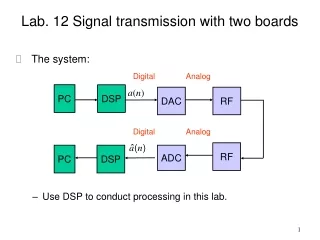
High-Level Schematic Multipurpose DAQ 4 signals Control XPc Target Pump Intermediate Electronics 10 signals Input DAQ A/D Differential Amplifier HESA (Hall Effect Sensor Array) with 5V and Gnd 1 Relay (5V) Output DAQ Digital Counter 3 Phase-Currents Motor Controller Rotor Motor 1 Speed Command (50Hz PWM) PWM (Pulse Width Modulation) Amplifier AMB (Active Magnetic Bearing) 4 AMB-Currents 1 Relay(5V) 4 AMB Current Command (20K Hz PWM) Pump I/O Signal Force/Field Power Box Power Current 20
Interior Electronics (Proposed) Digital Data Communication System (Transmit) 12-bit A/D 6 Total 72 bits 6 signals Motor Differential/Summing Amps 6 Total Digital Data Communication System (Receive) Current Regulation System 7 signals X-bit DAC 7 Total x bits Proposed High-Level Schematic (INT) Pump 72 bits HESA Hall Effect Sensor Array 2 Total 5V 8 signals 12V 3 currents x bits 4 currents AMB Active Magnetic Bearing 2 Total 15V
Exterior Electronics (Proposed) Digital Data Communication System (Receive) Digital Data Communication System (Transmit) Proposed High-Level Schematic (EXT) Miniaturization Project Control XPc Target 72 bits 72 bits Motor Controller ? PWM Amps 4 Total x bits ?