Download

1 / 12
120 likes | 129 Vues
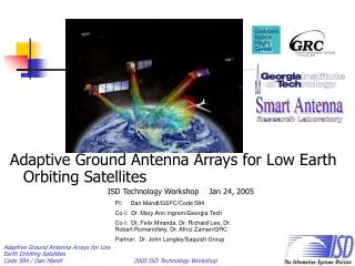
Adaptive Ground Antenna Arrays for Low Earth Orbiting Satellites ISD Technology Workshop Jan 24, 2005. PI: Dan Mandl/GSFC/Code 584 Co-I: Dr. Mary Ann Ingram/Georgia Tech Co-I: Dr. Felix Miranda, Dr. Richard Lee, Dr. Robert Romanofsky, Dr. Afroz Zaman/GRC

E N D
Adaptive Ground Antenna Arrays for Low Earth Orbiting Satellites ISD Technology Workshop Jan 24, 2005 PI: Dan Mandl/GSFC/Code 584 Co-I: Dr. Mary Ann Ingram/Georgia Tech Co-I: Dr. Felix Miranda, Dr. Richard Lee, Dr. Robert Romanofsky, Dr. Afroz Zaman/GRC Partner: Dr. John Langley/Saquish Group
Goals, Objectives, Benefits • Enable fabrication of cost effective antenna system for low earth orbiting satellites that act like wireless access points • Enable sensor webs
Vision to for Future Satellite Connectivity New Mission Paradigm: Flight and ground plug and play components connected with wireless access points Flight SW Bus Mission Critical Dynamic SW Bus Flight SW Bus Non-Critical Dynamic SW Bus Build satellite “Hot Spots” Hot-Loadable Flight SW Components Ground SW Bus Flight SW Bus
Adaptive Array Antennas Capabilities • Antenna patterns adjusted electronically thousands of times per second to follow users and avoid interference • Array can be built out of phased array elements or conventional antenna elements • Capability for multiple access on a single channel • Data rates vary per link according to the configuration of the adaptive array Antenna directional sensitivity
Related SensorWeb TasksUsing EO-1 as a Testbed Operational Testbed Autonomous Coordination End-to-End Communications On-board Processing Autonomous Sciencecraft Experiment(ASE) • Onboard planning • Onboard science processing • Autonomous/event driven processing On-board Cloud Cover Detection Validation (complete) Preliminary EO-1 Autonomy Experiment • On-board planning • On-board feature detection • Dynamic SW Bus (complete) EO-1 Sensor Web demos • MODIS trigger EO-1 fire & volcano images • SGM/ASE coordinates images autonomously • R/T GOES cloud screening Earth Phenomena Observing System (EPOS) (planning system) Science Goal Monitor(SGM) • Semi-autonomous coordination of imaging Smart Antenna • Ground phased array • “Cell tower” com to sat EO-1/ Gnd instr Sensor Web • Tiltmeters at Kilauea/Mauna Loa trigger EO-1 image EO-1 Volcano Sensor Web campaign Hyperspectral Compression WG • On-board data mining • On-board intelligent image compression • Working group Livingstone On-board Model Based Diag Tool • Autonomous anomaly diagnosis and recommendations Intelligent Distributed Spacecraft Technology Testbed Funded by ESTO Funded by NMP Funded by IS Proposed activity
A Proposal for a Lunar Adaptation Detail on multi-layer space-fed lens array Radome Mechanical support Circular tapered slot antenna Non Feed side Digital Control Feed side Multilayer Lens antenna array
Accomplishments and Planned Activities Adaptive Combining April 7, 2004 Successfully captured S-band data from EO-1, no steering Use 2- 4 mechanically steered small dishes to capture X-Band data from SAC-C (planned March 2004) Adaptive Combining Use 2 – 4 electronically steered antenna elements to capture X-Band data from SAC-C(planned Fall 2005)
Mechanical Steering Demo • Use SRS’s inflatable apertures mounted on positioner • Will use this system to capture 6 Mbps data from SAC-C in March 2005 GRC positioner
Electronic Steering Demo • Platform doesn’t move • Az/El control signals command beam directions • Phased arrays will be calibrated • Planned demo in Fall 2005 with SAC-C
Steering Control Computer Digital Control Interface Digital Control Interface az/el commands Steering Control Illustrations Radome Radome Mechanical support Mechanical support Steering Control Computer Digital Control Interface Digital Control Interface az/el commands Steering Control Computer Digital Control Interface az/el commands
Future Implications • Presently NASA Ground Network has spent about $2 – 4 million for each of the 11 meter antennas it uses • Usually resides in harsh climate • Mechanical drives decrease reliability • Not flexible • New technology can enable implementation of antenna systems as wireless access points • No moving parts • Support for multiple satellites • Flexible, software control • Potential to reduce cost by order of magnitude over presently used 11 meter dishes • Can enable internet type of connectivity thus facilitate new mission operations paradigm