Download
1 / 58
680 likes | 998 Vues
ENERGY MANAGEMENT SYSTEM Overview. Dr Shekhar KELAPURE. October 6, 2014. PSTI, Bangalore. What we cover. Load Dispatch Why EMS What is EMS Components of EMS Network Applications Framework State Estimator Power Flow & Optimal Power Flow

E N D
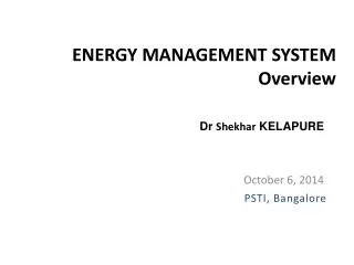
ENERGY MANAGEMENT SYSTEMOverview DrShekhar KELAPURE October 6, 2014 PSTI, Bangalore
What we cover • Load Dispatch • Why EMS • What is EMS • Components of EMS • Network Applications Framework • State Estimator • Power Flow & Optimal Power Flow • Contingency Analysis • Load Forecast What we do NOT cover • Generation Applications • Fault Analysis Dr Shekhar Kelapure
Load Dispatch • Objective -> Operate/Drive the Power System so that it is Stable Reliable Secure OPTIMAL Operate Power System “Efficiently” • What’s so big Dr Shekhar Kelapure
Why Energy Management System (EMS)? • What is expected from the “Dispatcher”? Stable/reliable/secure and optimal “Operation” What the “Dispatcher” need to know? • Complete knowledge about the system (Parameters and models of the System components) And • Knowledge of the Situation – “Situation Awareness” (Real – Time data of the system) EMS – Mechanism to capture “system knowledge” and “situation awareness” And provide key indicators Dr Shekhar Kelapure
What is Energy Management System? • Mechanism to hold the system knowledge • Mechanism to capture real time data (meas) Analog measurements (P, Q, V, F, “d”) Digital measurements (Status - CBs etc) • Validate the measurements • Analyze system performance using software programs and provide “key indicators” • Display data/measurements on “meaningful” displays • Send control commands to operate the system “efficiently” Dr Shekhar Kelapure
Components of EMS Network Application Generation Application Presentation Layer (DISPLAYS) Fault Analysis Unit Commitment/ Scheduling Contingency Analysis Reserve/Cost Monitoring Power Flow Optimal Power Flow Economic Dispatch Data Validation (State estimator) Automatic Generation Control Data Layer Load Forecast Data Acquisition (SCADA) Databases
Network Application Functions Objective – Analyze Power System performance from network (transmission and generation) perspective To check Base case violations Optimal performance (Loss Minimization etc.) Security Assessment & Enhancement Fault Analysis What we need – “GOOD” measurements – Load, Gen, Flows info. Transmission System Data – Capacities, R, X, B, Tap etc Generation Data – Ratings & other parameters Dr Shekhar Kelapure
NA Functions – used in EMS • State Estimator To identify Anomalies • Power Flow & Optimal Power Flow To carry out simulations To get optimal set-points • Contingency Analysis What if Analysis (N-1, N-2 etc) • Security Assessment and Enhancement Assessment and corrective actions • Load Forecast – Input to Simulations (NA functions) Dr Shekhar Kelapure
Objective : Filter out Dead system components Establish connectivity information and Define the LIVE(Energized) network withInputs : System Components Details, Switch Statuses and the Measurements (V, Power Flows, injections etc)Output : Live(energized) network details Formation of networks (Island wise) Mark viable islands (with Generation) Network Topology Dr Shekhar Kelapure
Network Topology Formation COMPONENT DETAILS GEN1 BUS1 GEN2 BUS2 GEN3 BUS3 SYNCON1 BUS6 SYNCON2 BUS8 TRANS1 BUS5 BUS6 TRANS2 BUS4 BUS9 LINE1 BUS1 BUS2 LINE2 BUS1 BUS5 LINE3 BUS2 BUS3 SWITCH DETAILS BUS1CB1 BUS1CB2 BUS1CB3 BUS1CB4 BUS2CB1 BUS2CB2 BUS2CB3 Dr Shekhar Kelapure
Network Topology – Node Terminology Incomer #2 Incomer #1 Nodes with Unique ID Secondary bus Bus Couplers Primary bus Outgoing #2 Outgoing #1 Dr Shekhar Kelapure
Real-Time Data superimposed on Line Network DIGITAL DATA BUS1CB1 CLOSE BUS1CB2 OPEN BUS1CB3 CLOSE BUS1CB4 CLOSE BUS2CB1 CLOSE BUS2CB2 CLOSE BUS2CB3 OPEN BUS2CB4 CLOSE BUS2CB5 CLOSE BUS2CB6 CLOSE BUS2CB7 OPEN BUS3CB1 OPEN ANALOG DATA P, Q FLOWS GENERATIONS VOLTAGES (ANGLES?) FREQUENCY 1.05-15.73 -0.135 - j 0.058 0.051+ j0.02 -0.015-j0.01 1.055-15.67 -0.061 - j 0.016 1.035-16.47 -0.149 - j 0.056 -0.17-j0.08 1.057-15.3 -0.035 - j 0.018 0.015+j0.01 1.052-15.51 -0.09 - j 0.058 -0.076-j0.025 1.057-15.3 -0.295 - j 0.166 0.17+j0.075 1.060.00 2.32 - j 0.17 0.065+j0.038 0.077-j0.026 1.07-14.83 -0.112 + j 0.068 -0.17+j0.017 0.75+j0.06 1.09-13.66 00 + j .172 1.57-j0.17 1.021-8.77 -0.076 - j 0.018 0.16-j0.003 -0.73+j0.053 1.02-10.34 -0.478 + j 0.039 -0.62+j0.16 0.63-j0.14 -0.55+j0.054 -0.40+j0.003 -1.53+j0.31 0.24-j0.36 0.42+j0.02 0.56-j0.003 0.73+j0.06 1.045-4.98 0.183 + j 0.295 -0.23+j0.045 -0.71+j0.038 1.01-12.73 -0.942 + j 0.44 Dr Shekhar Kelapure
Network Topology - Output CONNECTIVITY INFO ISLAND #1 GEN1 BUS1 GEN2 BUS2 GEN3 BUS3 SYNCON2 BUS8 TRANS1 BUS5 BUS6 TRANS2 BUS4 BUS9 LINE1 BUS1 BUS2 LINE2 BUS1 BUS5 LINE3 BUS2 BUS4 ISLAND #2 LOAD12 BUS12 Dr Shekhar Kelapure
Objective : Identify and correct Anomalies, Suppress Bad dataRefine the measurement set to form the State of the systemInputs : Energized System Components Details (Connectivity + Parameters) Switch Statuses (CBs, ISOs)Measurements (V, Power Flows, Loads, Generations)Tuning Parameters (Tolerances, Statistical Info etc)Output : Estimated complex voltages, Estimated P and Q injections and flows Error Analysis, List of Bad DataMethodology : Weighted Least Square (WLS) State Estimation Dr Shekhar Kelapure
System Info, Measurements and switch statuses Network Topology Observable? NO Add Pseudo Measurements YES State Estimator Refine Measurements Print results Voltage profile Loads and Generations Real/ reactive flows Meas Vs Estimates YES acceptable? NO Bad Data Processing Identify/suppress bad data State Estimator (SE) – Data Flow Dr Shekhar Kelapure
Measurements Bus Voltages Magnitudes (V) and Angles Generations (Pgen and Qgen)and Loads (PL and QL) Flows(real and reactive) at either end of lines/ transformer Size – 4 x Nlines(Flows) + Nbus (V) + Ngen (Gen)Output State variables (complex voltages at all buses – 2 x NBUS)? How many measurements are required?More measurements – slower the estimation process Less Measurements – erroneous results (poor estimation) Optimum - 1.5 to 2.8 times the state variables Measurements Dr Shekhar Kelapure
1.05 -0.135 - j 0.058 0.051+ j0.02 1.055 -0.061 - j 0.016 1.035 -0.149 - j 0.056 0.0+j0.0 -0.17-j0.08 2.32 - j 0.17 0.0+j0.0 1.057 -0.035 - j 0.018 1.052 -0.09 - j 0.058 0+j0 1.057 -0.295 - j 0.166 0.17+j0.075 1.06 2.32 - j 0.17 0.065+j0.038 0+-j0 1.07 -0.112 + j 0.068 -0.17+j0.017 0.75+j0.06 1.09 00 + j .172 1.57-j0.17 1.021 -0.076 - j 0.018 0.16-j0.003 -0.43+j0.053 1.02 -0.478 + j 0.039 -0.62+j0.16 0.63-j0.14 -0.55+j0.054 -0.40+j0.003 -1.53+j0.31 0.24-j0.360 0.42+j0.02 0.56-j0.003 0.73+j0.06 1.045 0.183 + j 0.295 0.23+j0.045 0+j0 1.01 -0.942 + j 0.44 Identify Measurement Errors INCONSISTANCIES FLOWS P15 AND P51 P23 AND P32 Q34 AND Q43 LOADS P12 Q12 V12 Dr Shekhar Kelapure
1.05 -0.135 - j 0.058 0.051+ j0.02 0.0 -0.0 - j 0.0 1.035 -0.149 - j 0.056 0.0+j0.0 -0.17-j0.08 2.32 - j 0.17 0.0+j0.0 1.057 -0.035 - j 0.018 1.052 -0.09 - j 0.058 0+j0 1.057 -0.295 - j 0.166 0.17+j0.075 1.06 2.32 - j 0.17 0.065+j0.038 0+-j0 1.07 -0.112 + j 0.068 -0.17+j0.017 0.75+j0.06 1.09 00 + j .172 1.57-j0.17 1.021 -0.076 - j 0.018 0.16-j0.003 -0.43+j0.053 1.02 -0.478 + j 0.039 -0.62+j0.16 0.63-j0.14 -0.55+j0.054 -0.40+j0.003 -1.53+j0.31 0.24-j0.360 0.42+j0.02 0.56-j0.003 0.+j0.0 1.045 0.183 + j 0.295 0.23+j0.045 0+j0 1.01 -0.942 + j 0.44 Suppress Erroneous Measurements REMOVE INCONSISTANCIES SUPRESS P51 P23 Q34 LOADS P12 = 0.0 Q12 = 0.0 V12 = 0.0 IGNORE OR REPLACE WITH APPROPRIATE VALUES Dr Shekhar Kelapure
Check Observability OBSERVABILITY Insufficient Measurements @ BUS10 and BUS11 1.05 -0.135 - j 0.058 0.051+ j0.02 1.057 -0.035 - j 0.018 0.0 -0.0 - j 0.0 1.035 -0.149 - j 0.056 0.0+j0.0 1.052 -0.09 - j 0.058 -0.17-j0.08 0.0+j0.0 0+j0 1.057 -0.295 - j 0.166 0.17+j0.075 1.06 2.32 - j 0.17 0.065+j0.038 0+-j0 1.07 -0.112 + j 0.068 -0.17+j0.017 0.75+j0.06 1.09 00 + j .172 1.57-j0.17 1.021 -0.076 - j 0.018 0.16-j0.003 -0.43+j0.053 1.02 -0.478 + j 0.039 -0.62+j0.16 0.63-j0.14 -0.55+j0.054 -0.40+j0.003 -1.53+j0.31 0.24-j0.360 0.42+j0.02 0.56-j0.003 0.+j0.0 1.045 0.183 + j 0.295 0.23+j0.045 0+j0 1.01 -0.942 + j 0.44 UNOBSERVABLE - Enable to estimate due to insufficient measurements “Calculations beyond the reach of available measurements” ??WHAT TO DO?? - - - - - - - - - - - - - - - - - - - - ADD PSUEDO MEASUREMENTS Dr Shekhar Kelapure
1.05 -15.73 -0.135 - j 0.058 0.051+ j0.02 0.0 -0.0 - j 0.0 1.035 -16.47 -0.149 - j 0.056 0.0+j0.0 -0.17-j0.08 0.0+j0.0 1.057-15.3 -0.035 - j 0.018 1.052-15.51 -0.09 - j 0.058 0+j0 1.057 -15.3 -0.295 - j 0.166 0.17+j0.075 1.06 0.00 2.32 - j 0.17 0.065+j0.038 0+-j0 1.07-14.83 -0.112 + j 0.068 -0.17+j0.017 0.65+j0.06 1.09-13.66 00 + j .172 1.56-j0.17 1.023 -8.77 -0.076 - j 0.018 0.18-j0.003 -0.63+j0.053 1.02-10.34 -0.478 + j 0.039 -0.59+j0.16 0.61-j0.14 -0.55+j0.054 -0.38+j0.003 -1.52+j0.31 0.18-j0.360 0.41+j0.02 0.56-j0.003 0.+j0.0 1.044 -4.98 0.183 + j 0.295 -0.17+j0.045 0+j0 1.012-12.73 -0.942 + j 0.44 Estimation Output ESTIMATES : Voltages 1 1.0600.00 1 1.044-4.980 1 1.012-12.73 1 1.020-10.34 Power Flows 1 2 1.56 –0.170 1 5 0.65 +0.060 2 1 –1.52 +0.31 2 4 0.55 –0.003 2 5 0.41 +0.020 Dr Shekhar Kelapure
1.05 -15.73 -0.135 - j 0.058 0.051+ j0.02 0.0 -0.0 - j 0.0 1.035 -16.47 -0.149 - j 0.056 0.0+j0.0 -0.17-j0.08 0.0+j0.0 1.057-15.3 -0.035 - j 0.018 1.052-15.51 -0.09 - j 0.058 0+j0 1.057 -15.3 -0.295 - j 0.166 0.17+j0.075 1.06 0.00 2.32 - j 0.17 0.065+j0.038 0+-j0 1.07-14.83 -0.112 + j 0.068 -0.17+j0.017 0.65+j0.06 1.09-13.66 00 + j .172 1.56-j0.17 1.023 -8.77 -0.076 - j 0.018 0.18-j0.003 -0.63+j0.053 1.02-10.34 -0.478 + j 0.039 -0.59+j0.16 0.61-j0.14 -0.55+j0.054 -0.38+j0.003 -1.52+j0.31 0.18-j0.360 0.41+j0.02 0.56-j0.003 0.+j0.0 1.044 -4.98 0.183 + j 0.295 -0.17+j0.045 0+j0 1.012-12.73 -0.942 + j 0.44 Bad Data Identification IDENTIFY BAD DATA Voltages Measu Estimat 1 1.060 1.060 2 1.045 1.044 3 1.010 1.012 4 1.020 1.0204 Power Flows Meas Estimat 1 2 1.57 1.56 1 5 0.75 0.65 2 1 –1.53 –1.52 2 4 0.56 0.55 2 5 0.42 0.41 Dr Shekhar Kelapure
1.05-15.73 -0.135 - j 0.058 0.051+ j0.02 -0.015-j0.01 1.055-15.67 -0.061 - j 0.016 1.035-16.47 -0.149 - j 0.056 -0.17-j0.08 1.057-15.3 -0.035 - j 0.018 0.015+j0.01 1.052-15.51 -0.09 - j 0.058 -0.076-j0.025 1.057-15.3 -0.295 - j 0.166 0.17+j0.075 1.060.00 2.32 - j 0.17 0.065+j0.038 0.077-j0.026 1.07-14.83 -0.112 + j 0.068 -0.17+j0.017 0.75+j0.06 1.09-13.66 00 + j .172 1.57-j0.17 1.021-8.77 -0.076 - j 0.018 0.16-j0.003 -0.73+j0.053 1.02-10.34 -0.478 + j 0.039 -0.62+j0.16 0.63-j0.14 -0.55+j0.054 -0.40+j0.003 -1.53+j0.31 0.24-j0.36 0.42+j0.02 0.56-j0.003 0.73+j0.06 1.045-4.98 0.183 + j 0.295 -0.23+j0.045 -0.71+j0.038 1.01-12.73 -0.942 + j 0.44 Bad Data Suppression OMIT BAD MEAS Power Flows Meas Estimat 1 5 0.75 0.65 5 1 –0.43 -0.63 Dr Shekhar Kelapure
1.05-15.73 -0.135 - j 0.058 0.051+ j0.02 -0.015-j0.01 1.055-15.67 -0.061 - j 0.016 1.035-16.47 -0.149 - j 0.056 -0.17-j0.08 1.057-15.3 -0.035 - j 0.018 0.015+j0.01 1.052-15.51 -0.09 - j 0.058 -0.076-j0.025 1.057-15.3 -0.295 - j 0.166 0.17+j0.075 1.060.00 2.32 - j 0.17 0.065+j0.038 0.077-j0.026 1.07-14.83 -0.112 + j 0.068 -0.17+j0.017 0.75+j0.06 1.09-13.66 00 + j .172 1.57-j0.17 1.021-8.77 -0.076 - j 0.018 0.16-j0.003 -0.73+j0.053 1.02-10.34 -0.478 + j 0.039 -0.62+j0.16 0.63-j0.14 -0.55+j0.054 -0.40+j0.003 -1.53+j0.31 0.24-j0.36 0.42+j0.02 0.56-j0.003 0.73+j0.06 1.045-4.98 0.183 + j 0.295 -0.23+j0.045 -0.71+j0.038 1.01-12.73 -0.942 + j 0.44 Final Estimation This becomes the “base case” for the remaining Network Analysis Functions Dr Shekhar Kelapure
Objective : To compute the power flow in the branches thru the complex voltages for given load/ generation profileInputs : system information component parameters and connectivity load and generation profile, voltage set-pointsoutput : voltage profile (voltage magnitude and angles) power flow calculations loss calculation violations (voltage magnitude and power flows) “MODELLING IS CRUCIAL” Power Flow Dr Shekhar Kelapure
Kirchhoff’s current Law Power Injection at ith bus Si = Vi x Ii*?? Set of Simultaneous Non-linear equations ?? Gauss Seidel (only for very small systems) Newton Raphson (Normally used) Fast Decoupled (Modified Newton Raphson) Power Flow – Basic equations To bus 1 V1 To bus k Vk To bus j Vj Yik Yi1 Yij Vi ith bus Yii Dr Shekhar Kelapure
Non-linear eqns Linearize & solve IterativelyCharacteristicsQuadratic ConvergenceNormally 3-5 iterations ReliableDifficulty - Handling Large Matrices Newton Raphson based Power Flow What’s way out? Try de-coupling ?FDLF? Assumptions 1. |V| ~ 1.0 p.u. Bus angle ) very small 2. Sin()=0 3. Cos()=1 4. R << X Dr Shekhar Kelapure
Power Flow, Inputs and Output INPUTS System DATA LINE DETAILS(RXB) XMER DETAILS(RXT) GENERATOR DATA(QLT) SHUNT DATA(B) LOAD/GEN DATA LOAD DATA GENERATION DATA(PV) TUNING PARAMETERS OUTPUT SLK – Pgen , Qgen PV - δ , Qgen PQ - δ , |V| In addition Branch Pflow , Qflow LOSSES PL , QL SHUNT POWER Dr Shekhar Kelapure
IEEE Format 08/19/93 UW ARCHIVE 100.0 1962 W IEEE 14 Bus Test Case BUS DATA FOLLOWS 14 ITEMS 1 Bus 1 HV 1 1 3 1.060 0.0 0.0 0.0 232.4 -16.9 0.0 1.060 0.0 0.0 0.0 0.0 0 2 Bus 2 HV 1 1 2 1.045 -4.98 21.7 12.7 40.0 42.4 0.0 1.045 50.0 -40.0 0.0 0.0 0 3 Bus 3 HV 1 1 2 1.010 -12.72 94.2 19.0 0.0 23.4 0.0 1.010 40.0 0.0 0.0 0.0 0 4 Bus 4 HV 1 1 0 1.019 -10.33 47.8 -3.9 0.0 0.0 0.0 0.0 0.0 0.0 0.0 0.0 0 5 Bus 5 HV 1 1 0 1.020 -8.78 7.6 1.6 0.0 0.0 0.0 0.0 0.0 0.0 0.0 0.0 0 6 Bus 6 LV 1 1 2 1.070 -14.22 11.2 7.5 0.0 12.2 0.0 1.070 24.0 -6.0 0.0 0.0 0 7 Bus 7 ZV 1 1 0 1.062 -13.37 0.0 0.0 0.0 0.0 0.0 0.0 0.0 0.0 0.0 0.0 0 8 Bus 8 TV 1 1 2 1.090 -13.36 0.0 0.0 0.0 17.4 0.0 1.090 24.0 -6.0 0.0 0.0 0 9 Bus 9 LV 1 1 0 1.056 -14.94 29.5 16.6 0.0 0.0 0.0 0.0 0.0 0.0 0.0 0.19 0 10 Bus 10 LV 1 1 0 1.051 -15.10 9.0 5.8 0.0 0.0 0.0 0.0 0.0 0.0 0.0 0.0 0 -999 BRANCH DATA FOLLOWS 20 ITEMS 1 2 1 1 1 0 0.01938 0.05917 0.0528 0 0 0 0 0 0.0 0.0 0.0 0.0 0.0 0.0 0.0 1 5 1 1 1 0 0.05403 0.22304 0.0492 0 0 0 0 0 0.0 0.0 0.0 0.0 0.0 0.0 0.0 2 3 1 1 1 0 0.04699 0.19797 0.0438 0 0 0 0 0 0.0 0.0 0.0 0.0 0.0 0.0 0.0 2 4 1 1 1 0 0.05811 0.17632 0.0340 0 0 0 0 0 0.0 0.0 0.0 0.0 0.0 0.0 0.0 2 5 1 1 1 0 0.05695 0.17388 0.0346 0 0 0 0 0 0.0 0.0 0.0 0.0 0.0 0.0 0.0 3 4 1 1 1 0 0.06701 0.17103 0.0128 0 0 0 0 0 0.0 0.0 0.0 0.0 0.0 0.0 0.0 4 5 1 1 1 0 0.01335 0.04211 0.0 0 0 0 0 0 0.0 0.0 0.0 0.0 0.0 0.0 0.0 4 7 1 1 1 0 0.0 0.20912 0.0 0 0 0 0 0 0.978 0.0 0.0 0.0 0.0 0.0 0.0 4 9 1 1 1 0 0.0 0.55618 0.0 0 0 0 0 0 0.969 0.0 0.0 0.0 0.0 0.0 0.0 5 6 1 1 1 0 0.0 0.25202 0.0 0 0 0 0 0 0.932 0.0 0.0 0.0 0.0 0.0 0.0 6 11 1 1 1 0 0.09498 0.19890 0.0 0 0 0 0 0 0.0 0.0 0.0 0.0 0.0 0.0 0.0 6 12 1 1 1 0 0.12291 0.25581 0.0 0 0 0 0 0 0.0 0.0 0.0 0.0 0.0 0.0 0.0 6 13 1 1 1 0 0.06615 0.13027 0.0 0 0 0 0 0 0.0 0.0 0.0 0.0 0.0 0.0 0.0 -999 END OF DATA Dr Shekhar Kelapure
Power Flow Results BUS WISE DETAILED RESULTS results for bus number 1 voltage(pu) 1.0600 angle(deg) -.0001 flow to (MW/MVAr) 2 1.5689 -.1744 flow to (MW/MVAr) 8 .7549 .0610 line charging (MVAr) -.0573 shunt injection (MVAr) .0000 Injections P/Q (MW/MVAr) 2.3238 -.1707 **************************************************************** results for bus number 2 voltage(pu) 1.0450 angle(deg) -4.9830 flow to (MW/MVAr) 1 -1.5259 .3056 flow to (MW/MVAr) 3 .7325 .0595 flow to (MW/MVAr) 6 .5629 -.0027 flow to (MW/MVAr) 8 .4136 .0243 line charging (MVAr) -.0917 shunt injection (MVAr) .0000 Injections P/Q (MW/MVAr) .1830 .2950 **************************************************************** BUS WISE RESULTS IN TABULATED FORM sr_no bus_no v_mag v_angle(rad) p_inj q_inj 1 1 1.0600 .0000 2.3238 -.1707 2 2 1.0450 -.0870 .1830 .2950 3 3 1.0100 -.2221 -.9420 .0440 4 4 1.0700 -.2589 -.1120 .0682 5 5 1.0900 -.2385 .0000 .1716 6 6 1.0186 -.1805 -.4780 .0390 7 7 1.0623 -.2385 .0000 .0000 8 8 1.0207 -.1532 -.0760 -.0180 9 9 1.0567 -.2673 -.2950 -.1660 10 10 1.0517 -.2708 -.0900 -.0580 11 11 1.0573 -.2671 -.0350 -.0180 12 12 1.0551 -.2735 -.0610 -.0160 13 13 1.0503 -.2745 -.1350 -.0580 14 14 1.0351 -.2875 -.1490 -.0560 ********************************************************** SUMMARY ******************************************************** total generation P/Q (MW/MVAr) 2.5068 .4081 total load P/Q (MW/MVAr) -2.3730 -.3510 system losses P/Q (MW/MVAr) -.1339 -.5522 total charging (MVAr) .2830 total shunt power (MVAr) .2122 ******************************************************** OR You can print them in “IEEE Format” exactly same as input So that other programs can read it easily Dr Shekhar Kelapure
Objective : Optimize the system parameters for better performanceInputs : System information (parameters & connectivity) load and generation profile, set-points(V, t, MW) component modeling and constraintsOutput : Voltage profile (voltage magnitude and angles) Optimized power flow calculations Violations (V, MW, MVAr) – remaining Major difficulty : Getting well-behaved objective function and constraints as function of control variables Optimal Power Flow Dr Shekhar Kelapure
Objective : Minimize PLOSS or Overload AlleviationsSubject to : Satisfaction of load flow equations (Power Balance) Limits on the control variables (set-points) Limits on line/transformer loading Maintain Load Generation BalanceControl Variables : Real Power Controls : MW Gen, Tie-Line Flows, HVDC/FACTS set-points Reactive Power Controls Generator voltage set-points VAr resources (Capacitors, Reactors, SVCs, Syn. condensers) Transformer taps HIGHLY NON-LINEAR PROBLEM – Solved using Gradient, SLP or any other method Problem Formulation Dr Shekhar Kelapure
C BSH_14 = 0.00 0.97-23.7 -0.189 - j 0.0812 0.073+ j0.036 -0.022-j0.013 0.98-23.6 -0.085 - j 0.022 0.94-24.88 -0.209 - j 0.078 -0.24-j0.104 -0.07 - j 0.03 0.983-23.0 -0.049 - j 0.025 0.022+j0.013 0.97-23.3 -0.126 - j 0.0812 -0.107-j0.036 1.057-15.3 -0.295 - j 0.166 0.247+j0.11 1.060.00 3.36 + j 0.41 0.091+j0.062 0.11+j0.039 1.0-22.27 -0.15 + j 0.13 -0.23-j0.01 1.08+j0.27 1.037-20.28 00 + j .24 2.28+j0.19 0.97-12.67 -0.106 - j 0.025 0.226+j0.041 -1.02-j0.03 0.96-15.03 -0.67 + j 0.054 -0.87+j0.14 0.88-j0.10 -0.77+j0.028 -0.57-j0.03 -2.18+j0.08 0.33-j0.08 0.59+j0.09 0.80+j0.08 1.05+j0.15 1.015-6.99 0.256 + j 0.322 -0.32+j0.10 -0.99+j0.065 0.96-18.88 -1.319 + j 0.134 Power Flow Base case LOSS REDUCTION REAL POWER LOSSES (UNOPTIMISED) BSH_14=0.0 0.2893 p.u. Dr Shekhar Kelapure
C BSH_14 = 0.05 0.99-23.54 -0.189 - j 0.0812 0.072+ j0.017 -0.021-j0.009 0.995-23.42 -0.085 - j 0.022 0.97-24.86 -0.209 - j 0.078 -0.24-j0.09 -0.07 - j 0.03 0.997-22.8 -0.049 - j 0.025 0.021+j0.009 0.99-23.1 -0.126 - j 0.0812 -0.106-j0.032 1.057-15.3 -0.295 - j 0.166 0.244+j0.098 1.060.00 3.35 + j 0.34 0.091+j0.061 0.10+j0.035 1.02-22.09 -0.16 + j 0.13 -0.23-j0.003 1.08+j0.25 1.048-20.18 00 + j .24 2.27+j0.15 0.98-12.68 -0.106 - j 0.025 0.226+j0.028 -1.02-j0.006 0.97-15.02 -0.67 + j 0.054 -0.87+j0.14 0.88-j0.12 -0.77+j0.045 -0.57-j0.018 -2.18+j0.13 0.33-j0.08 0.59+j0.08 0.80+j0.07 1.04+j0.14 1.018-7.01 0.256 + j 0.322 -0.32+j0.10 -0.99+j0.073 0.96-18.82 -1.319 + j 0.134 OPF – Loss Minimization LOSS REDUCTION REAL POWER LOSSES (UNOPTIMISED) BSH_14=0.0 0.2893 p.u. REAL POWER LOSSES (OPTIMISED) BSH_14=0.05 0.2854 p.u. Loss Reduction 1.35% Dr Shekhar Kelapure
0.98-22.5 -0.189 - j 0.0812 0.072+ j0.036 -0.021-j0.013 0.992-22.42 -0.085 - j 0.022 0.97-24.86 -0.209 - j 0.078 -0.24-j0.10 -0.07 - j 0.03 0.994-21.8 -0.049 - j 0.025 0.022+j0.013 0.98-22.1 -0.126 - j 0.0812 -0.107-j0.036 1.00-21.73 -0.413 - j 0.232 0.244+j0.113 1.060.00 2.90 + j 0.28 0.090+j0.062 0.11+j0.039 1.014-21.11 -0.16 + j 0.13 -0.23-j0.008 1.00+j0.24 1.048-19.12 00 + j .24 1.897+j0.104 0.98-11.72 -0.106 - j 0.025 0.23+j0.039 -0.952-j0.026 0.97-13.95 -0.67 + j 0.054 -0.84+j0.14 0.85-j0.11 -0.79+j0.033 -0.60-j0.027 -1.835+j0.086 0.32-j0.08 0.62+j0.09 0.83+j0.083 1.059+j0.148 1.025-5.82 0.68 + j 0.322 -0.31+j0.10 -1.01+j0.068 0.97-17.61 -1.319 + j 0.134 OPF – Overload Alleviation Overload Min REAL POWER FLOWS (UNOPTIMISED) 1 2 2.27 1 5 1.08 G1 = 3.35 G2 = 0.256 REAL POWER FLOWS (OPTIMISED) 1 2 1.897 1 5 1.00 G1 = 2.90 G2 = 0.68 Dr Shekhar Kelapure
C BSH_14 = 0.05 0.99-23.54 -0.189 - j 0.0812 0.072+ j0.017 -0.021-j0.009 0.995-23.42 -0.085 - j 0.022 0.97-24.86 -0.209 - j 0.078 -0.24-j0.09 -0.07 - j 0.03 0.997-22.8 -0.049 - j 0.025 0.021+j0.009 0.99-23.1 -0.126 - j 0.0812 -0.106-j0.032 1.057-15.3 -0.295 - j 0.166 0.244+j0.098 1.060.00 3.35 + j 0.34 0.091+j0.061 0.10+j0.035 1.02-22.09 -0.16 + j 0.13 -0.23-j0.003 1.08+j0.25 1.048-20.18 00 + j .24 2.27+j0.15 0.98-12.68 -0.106 - j 0.025 0.226+j0.028 -1.02-j0.006 0.97-15.02 -0.67 + j 0.054 -0.87+j0.14 0.88-j0.12 -0.77+j0.045 -0.57-j0.018 -2.18+j0.13 0.33-j0.08 0.59+j0.08 0.80+j0.07 1.04+j0.14 1.018-7.01 0.256 + j 0.322 -0.32+j0.10 -0.99+j0.073 0.96-18.82 -1.319 + j 0.134 OPF – Voltage Alleviation Voltage Alleviation Voltage V_14 (UNOPTIMISED) BSH_14=0.0 0.94 p.u. Voltage V_14 (OPTIMISED) BSH_14=0.05 0.97 p.u. Dr Shekhar Kelapure
Objective : Evaluation of the system performance under outagesInputs : System information (Parameters and connectivity info) Load and generation profile, voltage set-points Component modeling, Rating of the equipmentOutput : List of CRITICAL contingencies leading to violations Approach : Approximate simulation Contingency Analysis Dr Shekhar Kelapure
List of credible outages (having more probability of occurrence) System Information and Base Case State Estimator Efficient Screening Ranking (Based on Per. Indices) Print results Ranking List Power Flow results for Top ranked outages Analysis Full Evaluation of Severe Outages Contingency Analysis – Flow Chart Dr Shekhar Kelapure
Possible outages : All lines, transformers, generators, shunts, loadsFor 14 bus sample system, Total number of single component outages 17 lines + 3 transformers + 2 generators + 3 shuntsTOTAL = 25 + (?multiple outages?)WHAT IF the System size is 1000 buses?Challenge : 1500 AC load flow simulations of 1000 bus systemTake considerable time Contingency Analysis – possible contingencies Dr Shekhar Kelapure
Filtering/Screening Criteria1. Probability of occurrence2. Use of approx. analysis likePower flow with less tolerance Power flow – 1 iteration, esp. for overload analysis Network equivalents (outage impact - local)Ranking SEVERE contingencies based on performance indices - overload index - voltage indexFull AC power flow analysis for top ranked contingencies Processing Approach 1500 Possible CTGs Credible CTGs 150 Severe CTGs 15 Dr Shekhar Kelapure
Normally used performance Indices - overload index - voltage index - Based on Type of limit violated and % violations Index = 1000 x Type of limit violated + (100 + %violation) e.g. Emergency limit violated by 12%Index = 2112 Severity Indices Limits Type 1 – Normal 2 – Emergency 3 – LoadShed Dr Shekhar Kelapure
Base Case Power Flow Results 1.05-15.73 -0.135 - j 0.058 0.051+ j0.02 -0.015-j0.01 1.055-15.67 -0.061 - j 0.016 1.035-16.47 -0.149 - j 0.056 -0.17-j0.08 1.057-15.3 -0.035 - j 0.018 0.015+j0.01 1.052-15.51 -0.09 - j 0.058 -0.076-j0.025 1.057-15.3 -0.295 - j 0.166 0.17+j0.075 1.060.00 2.32 - j 0.17 0.065+j0.038 0.077-j0.026 1.07-14.83 -0.112 + j 0.068 -0.17+j0.017 0.75+j0.06 1.09-13.66 00 + j .172 1.57-j0.17 1.021-8.77 -0.076 - j 0.018 0.16-j0.003 -0.73+j0.053 1.02-10.34 -0.478 + j 0.039 -0.62+j0.16 0.63-j0.14 -0.55+j0.054 -0.40+j0.003 -1.53+j0.31 0.24-j0.36 0.42+j0.02 0.56-j0.003 0.73+j0.06 1.045-4.98 0.183 + j 0.295 -0.23+j0.045 -0.71+j0.038 1.01-12.73 -0.942 + j 0.44 Dr Shekhar Kelapure
Example - Generator Outage 1.05-16.73 -0.135 - j 0.058 0.053+ j0.03 -0.016-j0.01 1.055-16.67 -0.061 - j 0.016 1.033-17.47 -0.149 - j 0.056 -0.17-j0.07 1.056-16.3 -0.035 - j 0.018 0.016+j0.01 1.05-16.51 -0.09 - j 0.058 -0.0767-j0.025 1.053-16.3 -0.295 - j 0.166 0.17+j0.078 1.060.00 2.75 - j 0.13 0.067+j0.044 0.077+j0.076 1.07-15.84 -0.112 + j 0.113 -0.17+j0.026 0.83+j0.09 1.09-14.67 00 + j .194 1.92+j0.09 1.012-9.66 -0.076 - j 0.018 0.16-j0.011 -0.80+j0.045 1.01-11.34 -0.478 + j 0.039 -0.65+j0.18 0.66-j0.16 -0.52+j0.114 -0.37+j0.06 -1.86+j0.10 0.24-j0.085 0.38-j0.036 0.53-j0.065 0.726-j0.04 1.025-5.91 -0.217 - j 0.127 -0.24+j0.097 -0.70+j0.14 1.01-14.00 -0.942 + j 0.20 Dr Shekhar Kelapure
Example – Line outage 1.05-17.45 -0.135 - j 0.058 0.046+ j0.03 -0.014-j0.01 1.055-17.4 -0.061 - j 0.016 1.034-18.06 -0.149 - j 0.056 -0.17-j0.08 -0.046 - j 0.026 1.056-16.9 -0.035 - j 0.018 0.014+j0.01 1.05-17.05 -0.09 - j 0.058 -0.0754-j0.026 1.055-16.8 -0.295 - j 0.166 0.17+j0.079 1.060.00 2.33 - j 0.10 0.057+j0.046 0.076-j0.027 1.07-16.6 -0.112 + j 0.117 -0.17+j0.025 0.91+j0.09 1.09-15.1 00 + j .187 1.42-j0.14 1.011-10.66 -0.076 - j 0.018 0.16-j0.003 -0.87+j0.074 1.012-11.66 -0.478 + j 0.039 -0.38+j0.15 0.38-j0.14 -0.72+j0.096 0.0+j0.0 -1.38+j0.25 0.149-j0.42 0.0+j0.0 0.75-j0.006 0.82+j0.05 1.045-4.49 0.183 + j 0.219 -0.148+j0.046 -0.79+j0.072 1.01-13.25 -0.942 + j 0.078 Dr Shekhar Kelapure
Objective : Evaluate optimal set-points to bring the system back to normal state in post contingency scenarioInputs : System information (Parameters and connectivity info) Load and generation profile, voltage set-points Component modeling and constraints List of severe contingenciesoutput : Post Contingency complex voltage profile (V, d) Power flow calculations (after implementing optimized controls)Two Approaches:Preventive ActionCorrective Action Security Constrained Optimization Dr Shekhar Kelapure
Objective : min Overloads OR Voltage excursionssubject to : Satisfaction of load flow equations Limits on the control variables (set-points) Maintain Load Generation Balance Minimum deviation in set-points Pre and post outage(each severe outage) constraintsControl Variables :1. Generator voltage setpoints2. VAr resources (capacitors, reactors, SVCs, syn. condensers)3. Transformer Taps 4. Generations (MW)5. Tie-Line Flows, HVDC/FACTs controllers SCO – Preventive Action (PA) Dr Shekhar Kelapure
Challenges : Single Big problem Large number of constraints (considering all outages together) Conflicts between constraints May lead to infeasible solution Costly (Contingency may not happen at all)Then WHY? For some severe contingencies, post-outage controls rescheduling may not be possible due to time limitations Preventive Action - Challenges Dr Shekhar Kelapure
Objective : min Overloads OR Voltage excursionssubject to : Satisfaction of load flow equations Limits on the control variables (set-points) Maintain Load Generation Balance Minimum deviation in set-pointsOnly Post outage constraints for specific contingencyControl Variables :1. Generator voltage setpoints2. VAr resources (capacitors, reactors, SVCs, syn. condensers)3. Transformer Taps 4. Generations5. Tie-Line Flows, HVDC/FACTs controllers SCO – Corrective Action Dr Shekhar Kelapure
Advantages :Since occurrence of contingency is NOT certain, keeping post contingency plans ready is better (Preparedness)Separate optimization problem for each outage case Sometimes it may NOT be possible to make changes after outageChallenges :Post contingency scenario – Time is crucialWhether to go for PA/CA? For severe contingencies where the execution of CA is not possible, then check the probability and consequences and implement PA Corrective Action Dr Shekhar Kelapure
Load Forecast Objective : To get the accurate forecast of system/ area loads Inputs : Load History (Normally stored from actual SCADA data) Loads are function Weather data Effective weather forecast Weather history data Formula to get derived forecast variable Planning Inputs Dr Shekhar Kelapure
Load Forecast Types Short Term: Forecast Load for next hour (for every 5 mins) Forecasting Emergencies in Operations (Real Time) Medium Term Forecast Load for a week (hourly forecast) Normally used in operations (daily planning) Long Term Forecast Load for “>” 1 Year (monthly forecast) Normally used in Planning Dr Shekhar Kelapure