Download
1 / 13
130 likes | 269 Vues
Stave 130 Geometry. Peter Sutcliffe ATLAS Strips WP4 Meeting 26 th March 14 Liverpool. Stave Dimensions – Top view. Critical Dimensions: Overall Length 1277 Width 115 – Taking into Consideration the Bus Tape Width SMC area 100 x 50 EOS at Z=0 to Silicon Edge 0.1mm

E N D
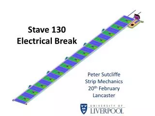
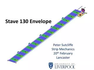
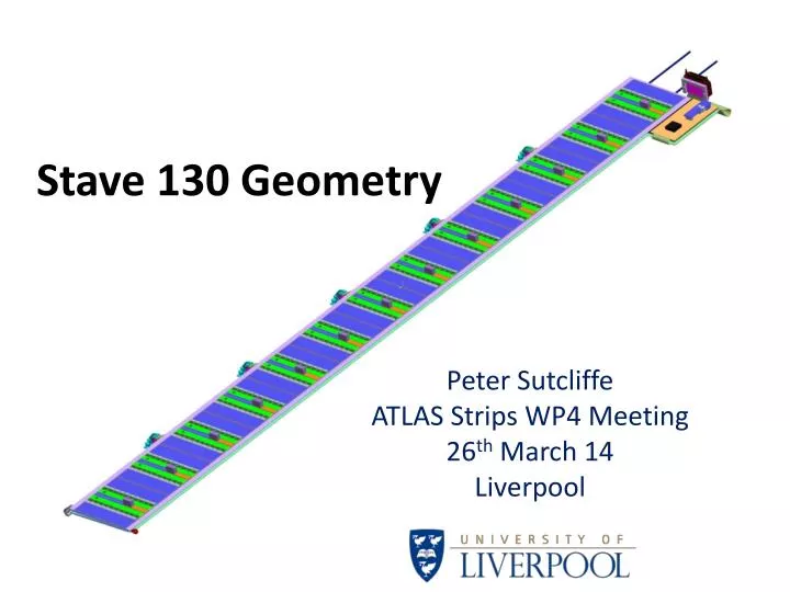
Stave 130 Geometry Peter Sutcliffe ATLAS Strips WP4 Meeting 26th March 14 Liverpool
Stave Dimensions – Top view Critical Dimensions: • Overall Length 1277 • Width 115 – Taking into Consideration the Bus Tape Width • SMC area 100 x 50 • EOS at Z=0 to Silicon Edge 0.1mm • Start of Silicon from Z=1277.1 = 3.36 • Module to Module Gap 0.46mm • Pitch of Modules 98mm
Stave Dimensions – Stereo Side Critical Dimensions: • EOS at Z=0 to Silicon Edge 0.1mm • Start of Silicon corner from Z=1277.1 = 1.45 • Module to Module Gap 0.38mm • Pitch of Modules 98mm • Stereo Angle 40mrad Stave length is determined by this corner of the last stereo module
Stave thicknesses Maximum wire bond height • Inner Skin to Inner skin 5.2 • KaptonBus to Kapton Bus 5.9 (co cured to carbon skin) • Wirebond to Wirebond 10.04mm • ASIC to ASIC 8.24mm
Z=0 End Closeout 3D Printed Model Z=0 Closeout manufactured from PEEK Stave to Stave Dimensions At Z=0
Z=1277.1mm End Closeout • Manufactured from PEEK • Machined or moulded • Closeout is sandwiched around the cooling tube and the Electrical Break ‘potted in’
Electrical Break 2.8mm Dia Ti Tube 2.8mm Dia Ti reducer Alumina insulator 2.275mm Dia Ti reducer 2.275mm Dia Ti Tube • Assembly vacuum brazed with silver copper eutectic • Brazing temperature around 780°C • Several have been manufactured and look good. Alumina insulator is very strong • Electrical break assembly is welded to the stave and inlet/exit tubes. • E break assembly is potted into the closeout Potted into end closeout Richard French End Closeout Carbon foam
Potential Clashes • Opto side –I think this will sort itself out i.e. slimmer opto packages or both opto packages on outer stave. • Clash with DCDC to Locking point • Possible solutions: • Place power tracks on the opposite side of tape • Make DCDC a planar coil with thickness less than 4mm • Reduce size of the cylinder mounted locking point • Something else…..…… Worst Case Inner layer with 10° stave angle and 7mm hign DCDC
Details of DCDC InterferenceWith 10°Stave angle (Layer 0) If 7mm DCDC box is used, the clash with the locking bracket is 1.58mm To obtain a clearance of say 2mm, the DCDC box would need to be 3.42mm
DCDC Continued… • Possible solutions for DCDC converter clash. • Reduce the height to 5mm from 7mm • This would still only give 2mm clearance to the locking point. Is this enough for installation tolerances? • Rotate the stereo modules 180° • This would mean having the power on the stereo tape on the opposite side of the stave i.e. locking bracket side. • Shrinking the PCB board? • Not sure as it may clash with the wire bonds…potential disaster. Power side