Download
1 / 9
90 likes | 218 Vues
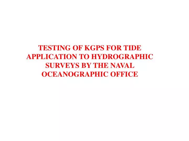
TESTING OF KGPS FOR TIDE APPLICATION TO HYDROGRAPHIC SURVEYS BY THE NAVAL OCEANOGRAPHIC OFFICE. Objectives of the Test Plan are to determine: - Accuracy - Methods - Procedures. Gulfport Base Station. LSU-1 Tide Gage 7 N.M. ACOE Tide gage 10 N.M. GULFPORT. Base Station.

E N D
TESTING OF KGPS FOR TIDE APPLICATION TO HYDROGRAPHIC SURVEYS BY THE NAVAL OCEANOGRAPHIC OFFICE
Objectives of the Test Plan are to determine: - Accuracy - Methods - Procedures
GulfportBase Station LSU-1 Tide Gage 7 N.M. ACOE Tide gage 10 N.M.
GULFPORT Base Station Tide gage KGPS Buoy
Test Plan: - Establish an offshore tide gage - Measure the distance between spheroid and chart datum at the gage - Place a KGPS buoy alongside the tide gage - Run survey lines near the buoy in kinematic mode to correct for tides (Real time and post-processing) - Compute buoy chart datum distance from spheroid and compare to tide gage distance - Compare kinematic tide corrections to tide gage corrections
BUOY CAPABILITIES Buoy Dimensions: Hull diameter 6.25 feet Overall height: 17 feet Weight: 900 lbs Sensors: 3-axis Acceleration 3-axis Magnetometer Vertical Reference Hull depth pressure sensor GPS- Novatel OEM4 L1/L2 with GPS600 antenna CPU and 20 GB HDD Power: Four solar panels Sealed batteries Warning system: Flashing obstruction light Radar reflector
s = seasonal change n= no.of obs. Zoo = distance of long term MSL to chart datum C = vertical distance from phase center to water surface while stable WGS-84 Ellipsoid . b a Buoy phase center C + accel. & tilt corr. Water surface t Observed MSL Zoo - s Chart Datum
ERROR SOURCES: - Squat-settlement will have to be removed from GPS height results to make a direct comparison with the tide gage. - Measured vertical distance at offshore gage from the GPS antenna to zero of gage not easily measured. - Receiver noise, multipath and distance from base station result in errors in GPS - Error occurs in datum transfer of chart datum - Acceleration and tilt errors occur at the buoy and vessel - Other systematic and random errors are possible