Download
1 / 8
80 likes | 205 Vues
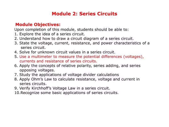
Module 2: Series Circuits Module Objectives: Upon completion of this module, students should be able to: 1. Explore the idea of a series circuit. 2. Understand how to draw a circuit diagram of a series circuit.

E N D
Module 2: Series Circuits Module Objectives: Upon completion of this module, students should be able to: 1. Explore the idea of a series circuit. 2. Understand how to draw a circuit diagram of a series circuit. 3. State the voltage, current, resistance, and power characteristics of a series circuit. 4. Solve for unknown circuit values in a series circuit. 5. Use a multimeter to measure the potential differences (voltages), currents and resistance of series circuits. 6. Apply the concepts of relative polarity, series adding, and series opposing voltages. 7. Study the applications of voltage divider calculations 8. Apply Ohm’s Law to calculate resistance, voltage and current in series circuits. 9. Verify Kirchhoff’s Voltage Law in a series circuit. 10.Recognize some basic applications of series circuits.
Series Circuits 2.1 Introduction to series circuits A series circuit is a circuit that has only one path for current flow. http://physiquecollege.free.fr/college_lycee/cinquieme/electricite/courts-circuits.swf Circuit Diagram Circuit diagram shows the physical details of the circuit. Schematic diagram uses symbols to represent each circuit component. Schematic diagram
Notes: In a series circuit: • If a lamp 'blows' or a component is disconnected, all the components stop working. • If you put more lamps into a series circuit, the lamps will be dimmer. 2.2 Identifying Circuit Components Current is the samein the series circuit In a series circuit, the total voltage equals the sum of the voltage across the batteries wired in series in the circuit. In a series circuit, the total resistance (in ohms) equals the sumof the resistance of each device using electricity.
2.4 Series Circuit Formulas IT = I1 = I2 = I3 VT = V1 + V2 + V3 RT = R1 + R2 + R3
Power in series circuits The total power dissipated (Pt) in a series circuit is always the sum of the power dissipated by the individual resistors or the product of the total current (It) and the source voltage (Vt). Two lamps are dimmer Single lamp is brighter PT = IT x VT Summary Table Ohm's Law can be used to solve for any of the individual values or for the total value of each measure within the series circuit.
2.5 Voltage Sources in Series When the polarities of the power sources are connected in the same direction as shown here, they are referred to as Series aiding When the polarities of power sources are connected in opposite directions as shown, their voltages cancel, and are referred to as Series opposing Solve example 1.1 - page 10
2.6 Voltage Divider Rule The two resistor voltage divider as shown here is used often to supply a voltage different from that of an available battery or power supply. The voltage drop across any given resistor in a series circuit is equal to Solve example 2.2- page 11
2.7 Kirchhoff's Voltage Law Kirchhoff’s voltage law (KVL) is generally stated as: Thesumof all the voltage drops around a single closed path in a circuit is equal to the total source voltage in that closed path. Solve exercises - page 17,18