Download
1 / 28
310 likes | 883 Vues
Asynchronous Transfer Mode (ATM). ATM is a specific asynchronous packet-oriented information, multiplexing and switching transfer model standard, originally devised for digital voice and video transmission, which is Based on 53-byte fixed-length cells.

E N D
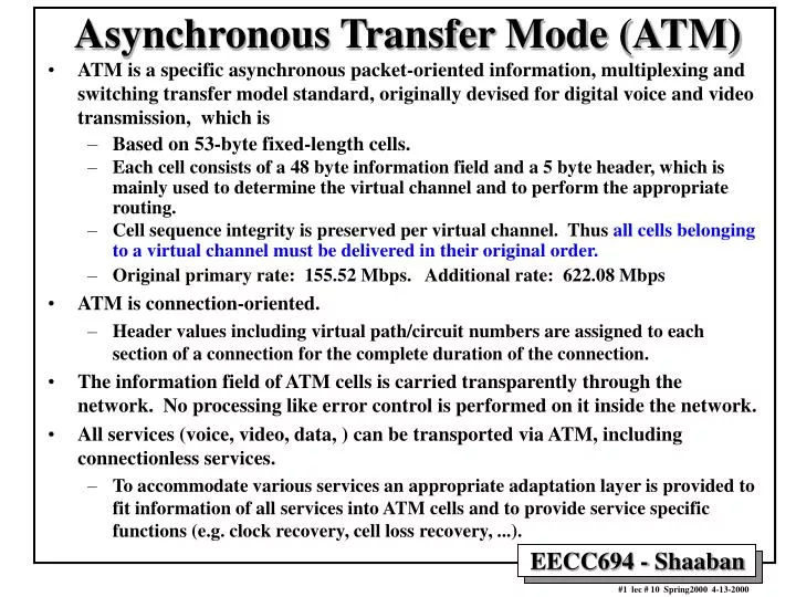
Asynchronous Transfer Mode (ATM) • ATM is a specific asynchronous packet-oriented information, multiplexing and switching transfer model standard, originally devised for digital voice and video transmission, which is • Based on 53-byte fixed-length cells. • Each cell consists of a 48 byte information field and a 5 byte header, which is mainly used to determine the virtual channel and to perform the appropriate routing. • Cell sequence integrity is preserved per virtual channel. Thus all cells belonging to a virtual channel must be delivered in their original order. • Original primary rate: 155.52 Mbps. Additional rate: 622.08 Mbps • ATM is connection-oriented. • Header values including virtual path/circuit numbers are assigned to each section of a connection for the complete duration of the connection. • The information field of ATM cells is carried transparently through the network. No processing like error control is performed on it inside the network. • All services (voice, video, data, ) can be transported via ATM, including connectionless services. • To accommodate various services an appropriate adaptation layer is provided to fit information of all services into ATM cells and to provide service specific functions (e.g. clock recovery, cell loss recovery, ...).
Synchronous Vs. Asynchronous Data Transmission Synchronous Transmission in a T1 Line Asynchronous Transmission in an ATM Line
Virtual Circuits • When a virtual circuit is established: • The route is chosen from beginning to end (circuit setup needed). • Routers or switches along the circuit create table entries used to route data transmitted on the virtual circuit. • Permanent virtual circuits - Switched virtual circuits
Fixed cell size = 53 bytes Input side Output side ATM Cells & Switches ATM Cell Format Cell Duration: ~ 2.7 msecfor 155.52 Mbps ATMs ~ 700 nsec for 622.08 Mbps ATMs An ATM switch
ATM Layer Headers 8 bits 1 16 bits 8 bits 4 bits 3 bits ATM layer header at User-Network Interface UNI 3 bits 1 8 bits 16 bits 12 bits HEC: ATM layer header at Network-Network Interface NNI
The Network Layer In ATM Networks • The ATM layer handles the functions of the network layer: • Moving cells from source to destination in order. • Routing algorithms within ATM switches, global addressing. • Connection-oriented without acknowledgments. • The basic element is the unidirectional virtual circuit or channel with fixed-size cells. • Two possible interfaces: • UNI (User-Network Interface): Boundary between an ATM network and host. • NNI (Network-Network Interface): Between two ATM switches (or routers).
ATM Network Connection Setup/Release Connection Setup Connection Release
ATM Virtual Path Re-routing Example Rerouting a virtual path re-routes all of its virtual circuits
ATM Routing Example Possible routes through the Omaha ATM switch
ATM Routing Example: Table Entries Table entries corresponding to routes through the Omaha ATM switch
ATM Switch Functions • The main function of an ATM switch is to relay user data cells from input ports to the appropriate output ports. The switch processes only user data cell headers and the payload is carried transparently. • As soon as the cell comes in through the input port, Virtual Path/Channel Identifiers (VPI/VCI) information is extracted from the cell and used to route the cells to the appropriate output port. • This function can be divided into three functional blocks: the input module at the input port, the cell switch fabric (or switch matrix) that performs the actual routing, and the output modules at the output ports. • Establishment and control of the VP/VC connections. • Unlike user data cells, information in signaling or control cells payload is not transparent to the network. • The switch identifies signaling cells, and even generates some itself. • Connection Admission Control (CAC) carries out the major signaling functions required. • Signaling/control information may not pass through the cell switch fabric, and instead is exchanged through a separate signaling network. • Network management functions, concerned with monitoring the controlling the network to ensure its correct and efficient operation. • Fault management functions, • Performance management functions, • Configuration management functions. • Connection admission control, usage/network parameter control and congestion control, usually handled by input modules.
CAC SM OM OM OM IM IM IM Cell Switch Fabric ATM/ SONET Lines ATM/ SONET Lines : . : . Input Side Output Side A Generic ATM Switching Architecture } IM = Input Module OM = Output Module CAC = Connection Admission Control SM = Switch Management Switch Interface
ATM Switch Interface Input Modules • The input module first terminates the incoming signal (in case of a SONET signal) and extracts the ATM cell stream: • Signal conversion and recovery. • Processing SONET overhead, and cell delineation and rate decoupling. • For each ATM cell the following functions should be performed: • Error checking the header using the Header Error Control (HEC) field. • Validation and translation of VPI/VCI values. • Determination of the destination output port. • Passing signaling cells to CAC and OAM cells to Switch Management • Addition of an internal tag containing internal routing and performance monitoring information for use only within the switch.
90 Columns (bytes) ATM cells Scrambled ATM Cell Payload ATM cells 3 bytes line overhead + 1 byte path overhead per row ATM Over SONET Example • The 53 bytes ATM cells are mapped into STS-3c or OC-3 frame payload as shown: • An STS-3c frame has a payload capacity of 3 * (90 - 3 - 1) columns * 9 rows or 2340 bytes. • Because of the STS-3c payload capacity is not an integer multiple of the ATM cell, a cell is allowed to cross the frame boundary. STS-3c or OC-3 Frame 9 rows Cell continued in next frame
ATM Switch Interface Output Modules Prepare ATM cell streams for physical transmission by: • Removing and processing the internal tag. • Possible translation of VPI/VCI values. • HEC field generation. • Possible mixing of cells from CAC and Switch Management with outgoing cell streams. • Cell rate decoupling. • Mapping cells to SONET payloads and generation of SONET overhead. • Conversion of the digital bit stream to an optical signal.
Connection Admission Control (CAC) Establishes, modifies and terminates virtual path/channel connections. Responsible for: • Signaling ATM Adaptation Layer (AAL) functions to interpret or generate signaling cells. • Interface with a signaling network. • Negotiation of traffic contracts with users requesting new VPCs/VCCs. • Renegotiation with users to change established VPCs/VCCs. • Allocation of switch resources for VPCs/VCCs, including route selection. • Admission/rejection decisions for requested VPCs/VCCs generation of usage/network parameter control (UPC/NPC) parameters.
The Cell Switch Fabric • The cell switch fabric is primarily responsible for transferring cells between the other functional blocks (includes data cells and possibly signaling and management cells as well). Other possible functions include: • Cell buffering and queuing. • Traffic concentration and multiplexing • Redundancy for fault tolerance • Multicasting or broadcasting • Cell scheduling based on delay priorities • Congestion monitoring. • Fabric Connection Types: • Fully Interconnected fabrics. • Fabrics using Multistage interconnection networks (MINs).
Fully Interconnected ATM Switch Fabric • Independent paths exist between all N2 possible pairs of inputs and outputs. • Broadcast all incoming cells on separate buses to all outputs. • Address filters pass the appropriate cells to the output queues. Input Side Output Side
Fully Interconnected ATM Switch Fabric:The Knockout Switch Output Side
An ATM Switch Fabric Using MINs:Batcher-Banyan Output Side Input Side Switching fabric of a Batcher-Banyan ATM switch
Batcher-Banyan ATM Switch Cell Routing Example Four cells being routed through an 8-input Batcher-Banyan switch
ATM Switch Queuing Modes An ATM switch with input side queuing An ATM switch with output side queuing
ATM LANs LAN Emulation Server ATM LAN Emulation