Download
1 / 31
461 likes | 873 Vues
Propulsion Overview. MAE155A Dr. Nacouzi. Agenda. Introduction to Propulsion Propulsion Systems: Liquids, Solids, other Basic Propulsion Performance Essential Isentropic Equations Nozzle Design and Performance Example. Propulsion Overview. Launch & Space Propulsion Systems

E N D
Propulsion Overview MAE155A Dr. Nacouzi
Agenda • Introduction to Propulsion • Propulsion Systems: Liquids, Solids, other • Basic Propulsion Performance • Essential Isentropic Equations • Nozzle Design and Performance • Example
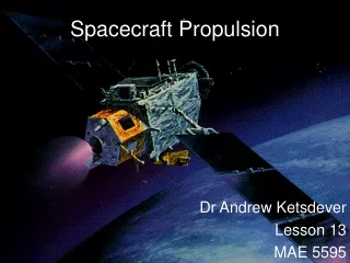
Propulsion Overview • Launch & Space Propulsion Systems • Propulsion system comprise the main component of a launch system. It can also be a significant (in terms of wt) component of the space vehicle (SV), depending on the SV’s mission • Delivers SV to proper orbit • Supports or provides means for interplanetary travel • Key component of many SV attitude control systems
Types of Propulsion Systems • Cold Gas: Pressurized Gas Expulsion, low Isp • Chemical Propulsion Systems: ‘Controlled Explosions’ • Liquid Systems: High Isp, throttle control, complex, most liquid propellants are toxic • Mono-propellant, usually used for SV ACS & Orbit maintenance, e.g. Hydrazine (long shelf life) • Bi-propellant, used for SV ACS and orbit maintenance as well as launch vehicle propulsion, e.g. MMH-Hydrazine, Cryogenic (LH2/LO2) • Dual Modes: Bi-propellant systems that can be used as mono-propellant (to minimize impulse bit)
Types of Propulsion Systems • Solid:Grain includes both fuel and oxidizer bound together, requires external ignition source (e.g., HTPB). • Simpler design, easier to handle, long shelf life • Low detonability, lower Isp than high energy bi-propellants, include metals to increase Isp, difficult to throttle control. • Consists of single or multiple pulses (restart option). May include thrust termination system. • Hybrid: Liquid oxidizer with solid fuel, throttle control • Gel Propellant: Safer storage than liquids, easier to throttle than solids, however viscosity makes flow management difficult, sensitive to temperature changes
Types of Propulsion Systems • Electric Propulsion:Used for space travel and orbit maintenance, very high Isp, low thrust and high energy input requirement • Electrothermal: Heats propellant using electric power (solar, nuclear or stored) • Electrostatic: Ion propulsion, involves ionizing gas and accelerating it to very high velocity by electrostatic fields • Electromagnetic: Plasma is accelerated by electric current and magnetic field • Other Propulsion Devices: Solar Sails, Laser propulsion...
Propulsion System Applications Note: Electric propulsion effective for interplanetary travel since high thrust is not typically needed
Cold Gas Systems • Cold Gas Systems: Involves the expulsion of high pressure gas
Liquid Propulsion System • Mono-propellant systems: Usually hypergolic fuel (no external spark needed), catalysis used to initiate chemical reaction • Bi-propellant systems: Fuel and oxidizer stored separately, mixed in combustion chamber at pre-determined mixture ratio and react hypergolically • Propellant pressurization can be regulated, i.e., external pressurant, or blowdown, i.e., in propellant tank
Bi-propellant Systems • Includes both fuel and oxidizer in separatetanks • Propellant managementthrough pressurant orturbine • Cryogenic systems muchmore complex due to temperature control
Pump Fed System: Liquid Engine Shematic • High flow rate • Complex, heavy systems Ref: University of Maryland
Solid Propulsion • Solid propulsion systems have good performance, are easy to handle, withstand shock, and less complex than liquid systems (few moving parts) • Difficult to check solid stages for internal cracks (although X ray may be used for small motors) • Cracks and failed bonds, can cause catastrophic termination due to increased burning surface area
Solid Propellant Rocket Motor Schematic - Casing holds and protects propellant - Thermal insulation applied on both outside and inside the casing to protect from both external and internal heating
Different Solid Grain Designs Chamber pressure, i.e., Thrust, can be tailored for mission
More Solid Grain Designs Comparison Progressive: Chamber pressure increases during burn Regressive: Chamber pressure decreases during burn Neutral: Approximately constant chamber pressure
Solid Propellant Burn Rate Burning rate, r, is the recession rate of a solid propellant and has units of length per time. The burning rate is estimated from: r = a Pcn where, a~ empirical constant fn of initial grain Temp & n~ burning rate pressure exponent Note that r is also a function of the propellant composition as well as other parameters.
Hybrid Rockets Concept Hybrid propulsion systems involve the injection of the oxidizer into a solid fuel. Main purpose is for throttle control. Simpler than a bipropellant system, Isp slightly lower.
Thrust Vector Control Various approaches to thrust vector control,TVC, are shown here Side Injection is also called LITVC (LiquidInjection TVC). Works by producing an asymmetrical nozzle flow, through an oblique shock,causing a nozzleside force.
Micropropulsion System (MEMS) Micro satellite ~ 1kg 15 Microthrusters on a chip impulse ~ 0.00001 N-s Used in DACS for Micro Sat
Ideal Rocket Assumptions • Ideal rocket equations are usually used to estimate the performance of a rocket. Assumptions: • Homogeneous & single (gaseous) phase products • Perfect gas, adiabatic & isentropic • Steady state, axial flow with uniform distribution • No chemical reactions past chamber, boundary layer, i.e., friction effects are ignored
Motor Thrust F ~ Thrust Pc~ Chamber Pressure Pe~ Exit Pressure Pa~ Ambient Pressure At~ Throat Area Ae~ Nozzle Exit Area Ve~ Gas Exit Velocity dm/dt ~ Gas Mass Flow Rate Sonic Line @ Throat (M = 1) F = dm/dt x Ve + (Pe - Pa) x Ae, Veq = Ve + (Pe - Pa) x Ae Exit Mach > 1 dm/dt
Basic Propulsion Equations Familiar specific impulse relationship: Isp = T/[(dm/dt) g] Total Impulse, I, is given by: => I ~ T x t We know, T = Veq x dm/dt = Isp (dm/dt) g => Isp = Veq/g Other definitions for Propulsion Measures of Performance: Thrust Coefficient, Cf: measure of nozzle performance efficiency Cf = T/(Pc At) ; Cf ~ fn(nozzle design, chamber conditions) where, T ~ Thrust, Pc ~ Chamber Pressure, At ~ Nozzle Throat Area
Basic Propulsion Equations Propulsion measure of performance: Characteristic velocity, C* (C star) is a measure of the energy available from the combustion chamber C* = Pc At/ (dm/dt) Combining Cf & C*, we get: Isp = T/ (dm/dt) g = Cf C* / g Therefore, given Cf and C*, the performance of the rocket can be evaluated. Cf is given by: ( )e ~ conditions at exit, ( )c in chamber, ( )a is ambient ~ ratio of specific heats
Basic Gas Dynamics Eqts Ideal nozzle performance is based on isentropic relations, calculated values are within a few percent of actual. Further improvements can be made using correction factors. Temperature as a function of Mach number and (gama) is given by: Where ( )0 is stagnation or chamber conditions Pressure and density relationships are similarly given by: ; Cstar is given by: &
Nozzle Flow Ideal Nozzle Relationships • Assumes isentropic flow • Nozzle Area Expansion given by = Ae/At (converging/diverging nozzle) where Ae is the nozzle exit area and At is the nozzle throat area - Flow is choked @ throat, M=1 - Pa (ambient) is < Pt (Pt is the throat pressure) Nozzle Exit, Ae (Me>1) Chamber, Pc M~0 Flow rate: Nozzle Throat, At (M=1)
Nozzle Performance • Exhaust Velocity is given by (Ref: Rocket Propulsion Elements, G. Sutton): => Exhaust Velocity for an ideally expanded nozzle ==> x ~ Ideal Cycle Efficiency
Nozzle Performance Approximate value for the ideal cycle efficiency => (Ref. Sutton) Area Expansion Ratio for a given exit pressure and gama:
Nozzle Performance Considerations • An ideally expanded nozzle has its exit pressureequal to the operating ambient pressure (1) => A nozzle operating in a vacuum would have an infinite expansion ratio… • Overexpanded nozzle (2): Pe < Pa • Oblique shock waves outside of exit plane • For higher Pa, flow separation & oblique shock waves are formed inside the nozzle • Underexpanded nozzle (3): Pe > Pa • Expansion waves @ exit plane to equalize pressure
Nozzle Performance Considerations • Fixed geometry nozzles cannot be designed to be optimal through their whole flight regime. Nozzle is underexpanded at ignition and overexpanded at burnout. Must be optimized for best overall performance. • When testing at sea level, nozzles are usually overexpanded (especially for upper stages). Adjustments to results and/or test article must be performed to account for ambient pressure differences...
Conclusions • Example Problem • Questions & Discussions...