Download

1 / 29
300 likes | 400 Vues
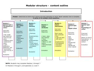
Nonlinear Analyses of Modular Coils and Shell structure for Cooldown and Modular Coil EM Loads Part 2 – Results of Clamp Assembly, Wing Bags, Poloidal Break Joints, and Flange Spacer Joints. H.M. Fan PPPL Nov. 15, 2005. FEA Model. FEA model simulates one field period.

E N D
Nonlinear Analyses of Modular Coils and Shell structure for Cooldown and Modular Coil EM Loads Part 2 – Results of Clamp Assembly, Wing Bags, Poloidal Break Joints, and Flange Spacer Joints H.M. Fan PPPL Nov. 15, 2005
FEA Model • FEA model simulates one field period. • Proper cyclically boundary conditions were applied on the boundaries. • Geometry imported from Pro/E model, which was provided by ORNL. • Small features, such as chamfers and fillers, in the geometry were removed to simplify meshing. • Model includes shells with tees and wings, wing bags, poloidal break spacers, toroidal flange spacers, modular coils, and simplified clamp assembly that consists of clamp, top pads, and side pads. • Modular coils are preloaded at side pads and top pads of the clamp assembly. • Contact behavior of modular coil is the standard frictionless unilateral contact. Right type C shell Right type B shell Right type A shell Left type A shell • Frictionless contacts were assumed between clamp pads and modular coils. • Wing bags are bonded to the wings and the adjacent shells. Left type B shell Left type C shell
Material Properties and Loadings • The following material properties are used: • Isotropic material properties were used for the modular coils. • Magnetic loads are based on 2T high beta current scenario at 0.0 seconds. • Differential shrinkage of coil cooling strain is 0.0004 m/m that is equivalent to a temperature reduction of 23.2558 °C. • Clamp preloads are generated by the thermal expansions of the side pads and top pads. • A temperature increase of 20 °C in the side pad provides a thermal strain of 2.5% that produces an initial preload of 556 N or 125 lbs. • A temperature increase of 4 °C in the top pad provides thermal strain of 0.5% that produces an initial preload of 92.6 N or 20.8 lbs.
EM Loads on Modular Coils • The vector plots of the EM loads show that force components Fθ and Fz of the same type coil pairs are opposite in direction in the cylindrical coordinate system and the Fr is in the same radial direction. • The net forces in the modular coils are: Top view • The six coils induce a net EM force of 5 MN toward the center. • The net vertical forces are downward in the right-hand-side coils and upward in the left-hand-side coils. Side view
Top view Contact Status of Top and Side Pads on Modular Coils • Most of top pads are in near contact condition that suggests a higher preload or higher CTE is needed if contact is desired. • Sliding contacts of the side pads are results of the sliding between coils and tees as the pads are bonded to the clamps. Pad locations Pad locations
Von Mises Stresses in Clamps • High stresses are found at where the clamps attached to the tee. • High stresses are primarily caused by the bending moments and the shear forces. • The maximum von Mises stress is 283 MPa at the clamp-tee interface. The stresses in the clamps are much smaller. Max. stress
Maximum Stresses at Clamp-Tee Interface • The plots show the locations and magnitudes for the contact pressure and frictional stress. • Positive pressure indicates load toward the surface and therefore is in compression. • The stress is primarily induced by the relatively thermal shrinkage between coil and tee during cooldown to 80°K. As the stress is a function of the shrinkage, the assumption that the initial shrinkage of coil strain of 0.0004 m/m should be verified and confirmed. • The EM load and clamp preloads also contribute forces in some degree. • The screw mounted at tee shall be designed for the forces and moments at this location. • Allowing sliding and the rotation at the screw joint will lower the force and moment. Contact pressure Contact friction stress
Contact Pressure on Wing Bags at Type AShell • Wing bags were assumed bonding to the shells in the analysis. • Positive pressure indicates load toward the surface and therefore is in compression. • Most effective spot on the wing bag locates near the cantilever end of the wing. • The areas with tensile contact pressure (negative sign) are not effective to transfer loads • Unit of contact pressure is Pascal. Left type A shell Right type A shell
Contact Pressure on Wing Bags at Right Type BShell • Wing bags were assumed bonding to the shells in the analysis. • Positive pressure indicates load toward the surface and therefore is in compression. • Maximum pressure appear at the left end of wing bag, bonded to type A shell • Similar contact pressure pattern occurs for the wing bags at the left type B shell • Unit of contact pressure is Pascal Right shell type B Contact pressure to shell type C Contact pressure to shell type B
Contact Pressure on Wing Bags at Right Type CShell • Rotational image of wing bag was bonded to the left type C shell with cyclically symmetric constraints to the original wing bag in the right type C shell. • Similar contact pressure pattern occurs for the wing bags at the left type C shell. Wing bag outside the 120° range Wing bag between shell types B and C Rotational image for wing bag outside the 120° range
Contact Pressures on Right Poloidal Breaks • Negative pressure is in tension that should be resisted by the bolt preload.. • Maximum compressive pressure appear at tee because of joint eccentricity with the shell. • On each plot pair, the right plot is the top view and the left plot is the bottom view. • Unit of contact pressure is Pascal Shell Type C Shell Type A Shell Type B
Contact Pressures on Left Poloidal Breaks • Negative pressure is in tension that should be resisted by the bolt preload. • The stress patterns are similar to the contact pressure patterns on the previous right poloidal breaks • Unit of contact pressure is Pascal Shell Type C Shell Type A Shell Type B
Contact Shear Stresses on Poloidal Breaks • The plots display the shear stress distributions on all poloidal breaks. • The net compression provided by the bolt preloads shall be able to produce enough frictional forces to withstand the shear forces in the poloidal breaks. Shell Type A Shell Type B Shell Type C
Joint Connections for Shell Flanges and Poloidal Breaks • Bolts and screws are used on the shell flange joints. • Studs use to locate two coils from flanges during assembly are not mechanical fasteners. • The nominal diameter of the bolt or screw is 1.375 inches • Because of the tight flange spacing, there are no bolts available at the inboard flanges. • The number of bolts and screws used at the shell flanges are as follow: 18 bolts and 2 screws at shell joint A-A 24 bolts and 3 screws at shell joint A-B 17 bolts and 12 screws at shell joint B-C, and 24 bolts and 8 screws at shell joint C-C • There are 7 bolts at each poloidal break. The total number of bolt in a field period is 42 bolts Shell type A Shell type B Shell type C Shell type C
Stresses Patterns are Sensitive to the Shape of Flange Spacer • The plots compare stress contours of the inboard flange spacers between the original shape and the revised shape at zero degree (flange joint A-A) using same contour values. • Three stress components are displayed in the cylindrical coordinate system (RSYS=1). Original shape Revised shape Normal stress Radial shear Stress Vertical shear stress
Normal Stresses in the Toroidal Direction for All of Inboard Flange Spacer Elements • For viewing clarity, the plots show only the nodal stress range between -80 MPa and 10 MPa in the cylindrical coordinate system. Stresses outside of the range are in grey color. • The minus sign indicates elements in compression. • Areas with red color are in tension that are not able to produce frictional force. • The plots demonstrates relatively symmetry in the stress pattern at comparable locations between the right spacers and the left spacers. • The plots reveal that higher wedge action occurs at inside than the outside due to constant spacer thickness. At 60° At 40° At 20° At 0° At -20° At -40° At -60°
Normal Stresses and Shear Stresses for theFlange Spacer Elements at 0° • Three stress Sy, Sxy, and Syz are displayed in the cylindrical coordinate system. • For clarity, contour plots only show the range within -80 MPa and 10 MPa for the normal stress and -16 MPa and 16 MPa for the shear stresses. Stresses outside of the range are in grey color. • The max. compression is 383 MPa and the max. tension is 72.2 MPa • Shear stress is the vector sum of Sxy and Syz. Without bolt connection at the inboard, the friction forces produced by the normal compression should provide safety margin for the shear forces. Normal stress Radial shear Stress Vertical shear stress
Normal Stresses and Shear Stresses for theFlange Spacer Elements at 20° • Three stress components are displayed in the cylindrical coordinate system. • For clarity, contour plots only show the range within -80 MPa and 10 MPa for the normal stress and -16 MPa and 16 MPa for the shear stresses. Stresses outside of the range are in grey color. • The max. compression is 129 MPa and the max. tension is 79.5 MPa • Similar stress pattern appears for the flange spacer elements at -20°. Normal stress Radial shear Stress Vertical shear stress
Normal Stresses and Shear Stresses for theFlange Spacer Elements at 40° • For clarity, contour plots only show the range within -80 MPa and 10 MPa for the normal stress and -16 MPa and 16 MPa for the shear stresses. Stresses outside of the range are in grey color. • The max. compression is 410 MPa, as shown on the left plot in a local area, and the max. tension is 43.6 MPa • Maximum shear stress occurs at the same location of the maximum compression Normal stress Radial shear Stress Vertical shear stress
Normal Stresses and Shear Stresses for theFlange Spacer Elements at 60° • Three stress components are display in the cylindrical coordinate system. • For clarity, contour plots only show the range within -80 MPa and 10 MPa for the normal stress and -16 MPa and 16 MPa for the shear stresses. Stresses outside of the range are in grey color. • The max. compression of 143 MPa and the max. tension of 47.4 MPa all found in the outboard spacer. Normal stress Radial shear Stress Vertical shear stress
No bolt connection No bolt connection No bolt connection No bolt connection At 60° At 40° At 20° At 0° Inboard Shell Flanges without Bolt Connections • The plots below show the ranges without bolt connection in the inboard flange. • The analysis assumed surfaces are bonded and no relative movement between contact surfaces. No bolt preloads were applied in the analysis. • Because of the net EM forces toward the center, the wedge action produces net compression at the inboard. The net forces at the outboard, however, are more in tension. • To prevent the sliding in the areas without bolt connection, the friction forces produced from the compressive forces shall be more than the shear forces. Otherwise, the shear resisting features, such as shear keys or shear studs should be added.
More on the Stresses on the Inboard Shell Flanges Joints • Since the EM load is dynamic in nature, the sliding on the joint is not recommended. • The maximum nodal shear stresses with corresponding normal stresses (minus is in compression) are: Shell Location Node Shear stress, MPa Nomal stress, MPa 0° 64937 209.4 (vector sum of 176.8 and 112.1) -384.2 20° 65441 46.2 (vector sum of 5.2 and 45.9) -129.9 40° 56942 55.4 (vector sum of 51.4 and 20.6) -342.7 60° 66906 26.6 (vector sum of 26.4 and 3.3) -46.8 • The ratio of the shear force to the compressive force determines whether the surface will be sliding or not. The ratio should be smaller than the coefficient of friction on the contact surfaces if no fasteners were provided. • Shear force and normal force shall practically be evaluated and averaged in small areas instead of at a nodal point. • From the above values, the impression is that the shear stress may be larger than the frictional stress produced by the normal compression. • For the inboard areas with tension (in red color), there are no frictional capability. • EM load is one of the major load in the system. The joint capacity and integrity should be checked during all loading stages, including assembly, dead weight, cool-down, all EM loads, seismic loads, and fault conditions. • The stress levels induced by the EM loads of the modular coils are much higher than the dead load. (Ref. to DL-analysis.ppt on email dated 9/16/2005)
Net Normal and Shear Forces at Inboard Flange Regions with No Bolt Connection • Local coordinates were defined on the flange surface to evaluate the normal and shear forces at a larger inboard area. The net forces, in Newton, are shown in the Tables below: • The total shear force is the vector sum of the horizontal shear and the vertical shear. • The horizontal shear forces are in the opposite direction at joints A-A, A-B, and C-C • The Shear-compression ratios range from 0.123 to 1.003
Bolt Connections at Shell Flanges and Poloidal Breaks • The wedge action of EM load produces net compression at the inboard. However, the net forces at the outboard are more and less in tension due to in-plane EM loads. • The preloads in the bolts shall be determined to overcome the tension and produce sufficiently frictional forces to resist the shear forces in the contact surfaces at all loading stages. • Effective preload in the bolt will be changed due to the temperature variation and the creep behavior of the materials in the joint. • When different materials are used for the bolt and shell structure, the bearing stress on the nut bearing area shall be checked with the highest possible preload. • For areas with screws, the capacity of thread engagement should be evaluated for the internal thread in the shell, particularly for locations with partial thread engagement as show below. • The calculation shall pay more attention to the first bolt or screw that is near the opening or the inboard region where no bolt connection exists. Partial Thread engagement
Discussion and Summary • In the analysis, the model assumed all surfaces in the shell structure were bonded and no bolt preloads were applied at the flanges and the poloidal breaks. • The main nonlinear effect comes from the frictionless contact behavior between the winding and the winding form. • From this analysis with cooldown and EM loads of the modular coils, the joint connection is judged to be a very critical issue in the shell structure, especially the flange spacer joint and the clamp-to-tee joint. • Joint compression and bolt preload shall be designed to produce enough frictional force to resist the joint shear force. • In the inboard regions where no bolts are available, the shear-compression ratios range from 0.123 to 1.003, greater than the hypothetical coefficient of friction, said 0.3. This indicates that the joint is not adequate unless the shear resisting features are added. • There are 5MN 0f net radial EM force induced by the modular coils in a field period. The vertical forces Fz and the toroidal forces Fθ in the coils are equal and opposite in direction for the right-hand side and the left-hand side, resulting in a zero net forces. • The normal forces in the flange spacer joints are the results of the Fr and Fθ of EM forces. The EM load in the modular coil produces net compression at the inboard leg region. Out side the region, the net forces in general are in tension. • The radial shear forces in the flange spacer joints are most likely caused by the non-uniform net radial forces from the modular coils and the irregular inboard flange shapes. • High local stresses were found in the flange spacers at the corners of the cut-out. Smoothing the shapes of flange spacers will minimize those peak local stresses.
Discussion and Summary (Continued) • Shear force and normal force at joints may be evaluated and averaged by small areas instead of at a nodal point to check the joint reliability and the bolt preloads. • The stress levels induced by the EM loads of the modular coils are much higher than the dead load (Ref. to DL-analysis.ppt on email dated 9/16/2005) • The initial expansion of the top pad is too low that makes the contact status at near contact situation. • The peak von Mises stress of 283 MPa in the clamp is based on the rigid mount of clamp to the tee. If sliding and rotation are allowed at the screw joint, the maximum stress will be lower. • The contact pressures on the wing bags are far from uniform. The contact surfaces are assumed to be bonded to the shells. The tension area in wing bag is not very effective for the load transfer. A shape change to minimized the tensile region will result in a more even stress distribution and lower compression. • The maximum contact pressure on the wind bag is 136 MPa (19.7 ksi). The load transfer through the wind bag is more or less proportional to its stiffness. • Contact pressure distribution on the poloidal break spacers are more even, except the narrow section in the tee. The bolt preload will be designed in opposition to the tensile stresses and shear stresses. • As the coil shrinkage during cool-down is the main factor of the nonlinear behavior, the assumption that the initial shrinkage of coil strain of 0.0004 m/m should be verified and confirmed. • The analysis is for modular coil with cool-down and EM load. The adequate joint design shall be able to withstand all possible load conditions.
Further Works • Additional data regarding stresses or forces at the poloidal break joint and the flange space joint shall be extracted to evaluate the bolt preloads and the joint performance. • At the inboard flange joints where no bolts are available, upgrading the shear resisting capability is needed. • A local model for the clamp assembly shall be used to investigate the clamp response to the maximum gap between tee and modular coil and the local deformation of tee. The results shall be used to design the screw that mounts the clamp to the tee. • The material property of the modular coil has direct effects on the results. As the accurate orthotropic material properties are not available, an upper bound and a lower bound material values may be used to estimate the results. • Complete analysis should include all loading stages, such as assembly stages, dead weight, cool-down, all EM loads, seismic loads, and fault conditions. • Although stress levels are lower for the dead load, its shear stress in the inboard flange surfaces shall be evaluated for the possible sliding. I f sliding may occur, additional load may be transferred to the first bolt (or screw). • The analysis assumed a coil shrinkage strain of 0.0004m/m for the equivalent coil cooldown. What is the impact on the results if the real relative strain between the winding and winding form varies from the assumed value? • The FEA assumptions are valid if the drop of 213°K to the cryogenic temperature does not changing the contact behavior of the wing bags and the relative elevation of the shell supports at the inboard and outboard stiffeners. If so, additional analysis may be needed.
Further Works (Continued) • Load path for the TF and PF coils should be well defined. The joint features that connect the TF structure to the shell structure shall be so planned that the radial EM forces from the TF coils will not transfer to the shell structure. • A model simulation at the inboard flange surfaces with frictional contact instead of the bonded contact will have better representation of the behavior at the inboard joint. However, accurate input of the bolt preload is difficult without including bolts in the model. In addition, a larger computer memory will be needed for the non-symmetric stiffness matrix that may be a problem for the existing available PC. • If the actual material property is different from the assumed value and is considered to have an impact on the results, the model should be rerun with the new material properties. • An analysis that includes all existing loads such as dead loads, cool-down effects, vacuum vessel loads, and all EM loads may be the governing load case. • A linear model consisting of all parts may be run for the verification purpose. This model will have more accurate load distribution from the TF structure and from the vacuum vessel. • The coefficient of friction on the surfaces shall be determined from reliable sources for properly estimating the joint frictional capability.
FEA Model and Result Data Base • filen9.db -- Nonlinear run with original geometry • filen9b.db -- The inboard flange spacer at joint A-A was modified as shown in slide 15