Download
1 / 35
360 likes | 744 Vues
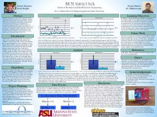
Sleep Easy Alarm Clock ECE 445 Senior Design. Daniel Kim Kevin Lee Jonathan Santos. Introduction. Five different stages of sleep in normal sleeping cycle Entire cycle lasts approximately 90 minutes If individual wakes up during light sleep, feels rested and alert

E N D
Sleep Easy Alarm ClockECE 445 Senior Design Daniel Kim Kevin Lee Jonathan Santos
Introduction • Five different stages of sleep in normal sleeping cycle • Entire cycle lasts approximately 90 minutes • If individual wakes up during light sleep, feels rested and alert • If individual wakes up during deep sleep, feels tired and groggy Freq (Hz) Brain Wave Sleep Stage 0.5 – 3 Delta Deep Sleep 1 & 2 4 – 8 Theta Drowsy Sleep 9 – 13 Alpha Light Sleep 14 + Beta REM, Awake
Objectives • Enable an alarm clock to monitor brain waves via electroencephalography (EEG) and process these signals using digital signal processing in order to wake the user during light sleep • Recognize when the user has fallen asleep and turn off specified appliances; recognize when the user has woken up, and turn on specified appliances.
Features • Digital clock display • Programmable alarm • Easy Usage • Ability to turn on and off appliances as you wake up and fall asleep, respectively
Block Diagram User Interface Signal Processing Circuit Alarm Clock Circuit EEG Circuit Display Circuit Relay Circuit
Project Build HR & MIN Increment Push Buttons 4-position switch Relay Circuit Banana Jack Inputs from Electrodes Appliance Control Switches Plexiglass Cover Display Circuit (Signal Processing Circuit and Alarm Clock Circuit below) EEG Circuit
EEG Circuit - Original Design • 2 Passive Bandpass Filters • LPF: 48 Hz • HPF: 0.48 Hz • 2 instrumentation amplifiers (AD622AN) • low DC offset • low drift • low noise • high open-loop gain
C17 R30 Left Electrode .1u 33k R29 U17 3.3mega .1u + U18 0 OUT + 0 Output - OUT C23 R40 AD622 Right Electrode - OPAMP .1u 33k R39 3.3mega 0 .1u Neck Electrode 0 0 EEG Circuit - Original Schematic
Gain Theoretical: Actual:
C17 R30 .1u 33k R29 3.3mega .1u 0 0 C7 R7 0.1u R11 R12 U7 3.3mega + C6 C5 U6 33k 33k OUT + C8 0.1u 0.1u 0.1u - OUT OPAMP R8 3.3mega - OPAMP 0 0 Passive vs. Active Filters
EEG Circuit – Final Design • 3 Ag/AgCl EEG electrodes • 2 placed on the forehead • 1 placed on the neck to ground the user • 3 Conductor Shielded Cable • 1 Quad Op-amp (MC3403) • 2 instrumentation amplifiers (AD622AN)
EEG Circuit – Demo Design • Replaced MC3403 with 4 LM741 • Only 1 AD622AN • Reduced Gain
New Gain Theoretical: Actual:
Simulated Frequency Response Actual Frequency Response
G~1000Vin = 1mVInput Freq = 75 HzVpp = .47 VInput Freq = 0.1 HzVpp = .231V
Block Diagram A/D 200 S/s Calculate Average V(t) Zero-cross algorithm: int16 old, new = 2 sequential samples; Num_zero_cross = 0; If (new < average AND old > average, OR new > average and old < average) Num_zero_cross ++; Frequency = Number_zero_cross ; 2*time_interval Outputs: If ( 9 < Frequency < 13) sigA = 1; Else sigA = 0; If (Frequency transitions from 13 Hz or higher to 8 Hz or lower) sigB = 1; Else sigB = 0; sigA sigB
Signal Processing PIC Design • Original design: calculate average on a sliding window. Allows for small changes in VDC to not affect calculation of frequency. • 2nd Design: Pseudo-average calculation: avg = (avg*199+new_sample)/200; • Final design: calculate average on a 1 second static window, repeat every 2 sec. • Reason for deviation: not enough buffer space to hold enough samples for sliding window; had problems with division and rounding errors
Signal Processing Analysis • Required outputs: SigA is high for frequencies between 9-13 Hz. SigB goes high on transition from above 14 Hz to below 8 Hz. • Actual SigA output: SigA is stable high for frequencies between 9.3-13.3 Hz. • Actual SigB output: SigB goes high on transition from 14.3 Hz to 8.4 Hz (minimum transition)
Desired response of SigA Actual response of SigA
Some notes on PICs • We achieved a stable high for SigA for frequencies between 9.3 Hz and 13.3 Hz. • During the demo, SigA was stable high for frequencies between 9.3 Hz and 11.5 Hz.
Alarm Clock Circuit • PIC16F877A • Piezo-buzzer • I/O Diagram: Relay1 Relay2 Alarm off Night Day Night Day Alarm on Set Alarm Hour Minutes Set Time Alarm Clock Relay1 sigA Relay2 sigB Buzzer
Keeping Time • Time is kept in variables, timeHour and timeMin. • Timer1 is a 16-bit internal counter that is incremented every 8 µs. It is set to 3036 as the initial value. Timer1 overflows every (2^16-3036)* 8 µs = 0.5 seconds. • On overflow, it calls an interrupt handler (every 0.5 seconds). When the interrupt handler is called 120 times, then a full minute has passed, and timeMin is incremented.
Buzzer • Conditions for the buzzer to sound: • If (sigA is high AND clockTime is within 90 minutes of the alarmTime) set off buzzer; If( clockTime == alarmTime) set off buzzer; Else, turn off the buzzer.
How accurate is the clock? PIC Time www.time.gov • Design Proposal: Accurate timekeeping to within 1 second every 24 hours. • Achieved Accuracy: In comparison to www.time.gov atomic clock, our clock seems to meet our initial requirement. www.time.gov is accurate to within 0.1 seconds Our reflex response to record time is accurate to at least within a second, if not better.
Display Circuit • 7-segment hex LEDs (LSD3211-11) • BCD to 7-segment decoders (CD4511)
User Interface Can you guess which picture was taken first?
Relay Circuit • Potter & Brumfield T77S1D10-05 • 10 amp PCB relay • Min. Contact Load • 10mA • 5VDC • MPS2222A NPN transistor
Recommendations • Order PCBs from outside vendors • Non-conductive box • Wireless headpiece (electrodes) • Combine 2 PICs into one to reduce cost • Design contained power supply • Additional sensing mechanisms • Multi-Channel EEG • Eye movement (EOG) • Temperature • Respiration • Pulse (EKG) • Muscle tension (EMG)
Acknowledgements • Professor Carney • Hyesun Park • Alex Spektor • ECE Parts Shop • ECE Machine Shop • Professor Fish