Download
1 / 47
470 likes | 581 Vues
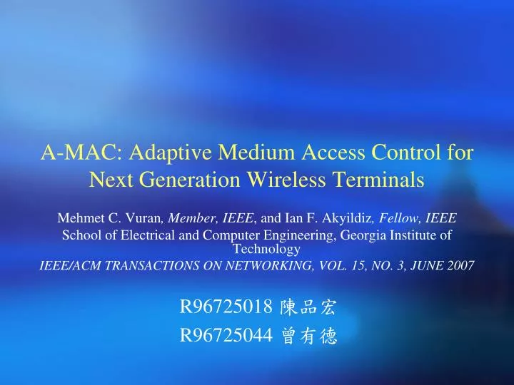
R96725018 陳品宏 R96725044 曾有德. Mehmet C. Vuran , Member, IEEE , and Ian F. Akyildiz , Fellow, IEEE School of Electrical and Computer Engineering, Georgia Institute of Technology IEEE/ACM TRANSACTIONS ON NETWORKING, VOL. 15, NO. 3, JUNE 2007.

E N D
R96725018陳品宏 R96725044曾有德 Mehmet C. Vuran, Member, IEEE, and Ian F. Akyildiz, Fellow, IEEE School of Electrical and Computer Engineering, Georgia Institute of Technology IEEE/ACM TRANSACTIONS ON NETWORKING, VOL. 15, NO. 3, JUNE 2007 A-MAC: Adaptive Medium Access Control for Next Generation Wireless Terminals
Outline • Introduction • Related Work • The Virtual Cube Concept • Network Modeling • A-MAC: Adaptive Medium Access Control • Performance Evaluation • Conclusion
Next Generation Wireless Networks • Next Generation (NG) wireless networks are envisioned to provide high bandwidth to mobile users via bandwidth aggregation over heterogeneous wireless architectures • The various types of MAC protocols: TDMA, CDMA, WCDMA and CSMA/CA • QoS classes: Conversational, streaming, interactive and background Fig. 1. Next generation wireless networks.
Challenges • Heterogeneity in Access Schemes: Different access schemes in different wireless networks • Heterogeneity in Resource Allocation: No unified metric for comparison of the allocated resources • Heterogeneity in QoS Requirements: The MAC layer must efficiently evaluate the available resources in different networks to satisfy the QoS requirements
The Structure and The Components of A-MAC • Two-layer Adaptive Medium Access Control (A-MAC) • Access sub-layer:Specialized for accessing the network • Master sub-layer:Perform decision and scheduling requests for the most efficient network • A novel Virtual Cubeconcept is used to model the networks Fig. 2. Main Components of A-MAC.
Main Object • Incompatibility among medium access and resource allocation techniques are melted into a unified medium access control framework, providing self-contained decision flexibility as well as capability to access various networks.
Related Works • An Ad-hoc CEllular NETwork (ACENET) • TCDMA protocol • Hybrid TD/CDMA systems • A multiple access protocol of cellular Internet and satellite-based networks • The proposed methods requires either a modification in the existing infrastructure and base stations or a completely new architecture • Integration problems: Implementation costs, scalability and backward compatibility
Assumption • NG wireless terminals are capable of receiving signals from multiple network access points and transmitting signals to different access schemes simultaneously.
III. The Virtual Cube Concept Resource-Space Virtual Cube Structure
Resource-Space • Time Dimension: The time required to transfer information • Rate Dimension: The data rate of the network • Power Dimension: The energy consumed for transmitting information through the network
Virtual Cube Structure • Three parameters: • Cube Capacity (M bits/cube) • Cube Power (P Watts/cube) • Cube Duration (T sec/cube) • Two types of virtual cubes are used in the A-MAC: • Virtual Information Cube (VIC): The information sent through the network • Virtual Power Cube (VPC): The additional power needed to transmit M bits of information VPC M VIC Fig.3. Virtual cube model.
IV. Network Modeling TDMA Modeling CDMA Modeling CSMA Modeling Multi-Rate Networks
TDMA Modeling • A TDMA slot is characterized by slot duration and transmission rate • Each interface is characterized by an average energy per bit • The number of virtual cubes that can be filled in three dimensions of a resource bin: (1) Fig. 4. (a) TDMA and CDMA modeling.
CDMA Modeling • Direct Sequence-CDMA (DS-CDMA) • each bit of duration is coded into a pseudo-noise code of chips of duration • the spreading gain • the transmitted energy per bit • is the bandwidth , is the data rate and is the transmitted signal power • TDD CDMA • the time is divided into radio frames, slots and sub-frames • is determined by the length of the allocated slot • FDD CDMA • is determined by the duration of the connection
CSMA Modeling • IEEE 802.11 • It is impossible to deterministically calculate the transmission time in CSMA based systems • Using the last transmission information to model the resource bin Fig. 4. (b) CSMA Modeling.
Multi-Rate Networks • Multi-code CDMA, e.g., IS-95-B and cdma2000 • The number of virtual cubes in the rate dimension, ,of the CDMA frame model increases with the data rate • The power level, ,for a CDMA signal with a spreading gain , where is the power level of the fundamental spreading gain and is the fundamental spreading gain Fig. 4. (c) Multi-code CDMA modeling.
Multi-Rate Networks (cont.) • Multi-channel communication, e.g., cellular networksand IEEE 802.11 standard • The number of virtual cubes in the rate dimension, , depends on many channel and transceiver dependent parameters such as the channel bandwidth, modulation and channel coding schemes Fig. 4. (c) Multi-channel modeling.
V. A-MAC: Adaptive Medium Access Control Decision Scheduling Adaptive Network Interfaces (ANIs)
The Structure and The Components of A-MAC Fig. 2. Main Components of A-MAC.
Decision • A-MAC performsdecision in each decisioninterval • For a specific traffic flow, the decision block chooses theinterface such that the utility function • Aims to findthe interface with maximum throughput capability for the minimumtransmission power (2)
Decision (cont.) • Constraints: • is the bandwidth share of the trafficin interface • is the maximum power dissipation allowed for the decision interval • is the minimum required bandwidth in termsof VICs for the traffic typein order to guarantee its QoSrequirements • is the set of active interfaces that arechosen by the decision block (3) (4)
Decision (cont.) • Single Type Traffic—Single Interface (STSI) • Single Type Traffic—Multiple Interfaces (STMI) • If the (3) and (4) are met by one or more interfaces, theone that maximizes (2) is chosen • else… • the interfaces are sorted in a decreasingorder of their utility functions • the constraint (4) becomes • A weight is associated with interface (5) (6)
Decision (cont.) • Multiple Type Traffic—Single Interface (MTSI) • checks if the decision constraints hold for each traffic type • each eligible traffic type is assigned a bandwidth share such that • checks if each flow satisfies (3) and (4) • the scheduler is informed of the bandwidth shares and MAC frame size of the interfaces • or the traffic type with the lowest priority is rejected and the bandwidth shares are updated • Multiple Type Traffic—Multiple Interfaces (MTMI)
Scheduling • In designing a scheduler, the requirements are considered: • QoS Guarantee • Channel Dependent Scheduling • Dynamic Behavior • Implementation Complexity • Bin Sort Fair Queuing(BSFQ) scheduler • Frame-based method • uses virtual time stamps to determine the scheduling order • Built-in buffer management component
Packets from the current bin are transmitted, and updates BSFQ method The current bin has the label τ( t) = t2 virtual system clock Δ Each bin is implicitly labeled with a virtual time interval and each interval has length Δ The output buffer is organized into N bins [ , + ) The i-th bin has the label [ , + ) 27 Fig. 1. Bin Sort Fair Queuing.
BSFQ method (cont.) • The output buffer is organized into N bins • Each bin is implicitly labeled with a virtual time interval and each interval has length Δ • The current bin has the label • The ith bin has the label • Only packets from the current bin are transmitted • Bin list is cyclic-list • The output link rate may changeduring the connection time due to wireless channel conditions • In order to preventfluctuations in the bandwidth share of flows, the schedulerupdates each bandwidth share in each decision interval 28
BSFQ method (cont.) • The jth packet of flow f is assigned with the virtual time stamp • is the arrival time of packet • is the length of • is the reserved data rate of f 29
BSFQ method (cont.) • The index of the bin used to store packet is equal to: • If =0 then is stored in the current bin. • If < N then is stored in the -th bin following the current bin. • If > N then the packet is discarded. 30
Adaptive Network Interfaces (ANIs) • Network Structure Awareness • gathering information about the underlying network structures • achieved in different wireless systems, i.e., GSM, UMTS, cdma2000, and WLAN • Network Modeling • ANIs model or update the network MAC structure (resource bin) and inform the master sub-layer • Access and Communication • An ANIperforms access to the network if it is selectedfor a transmission by the master sub-layer • The communicationwith the AP is performed according to the network specific procedures
VI. Performance Evaluation Traffic Models Network Models Simulation Results 32
Traffic Models Exponential distribution and statistically independent Modeling based on a three-step Morkov model. Exponential distribution The stations generate IP packets with length of 260 bits in every 20 seconds Exponential distribution The bit rate in each state is determined independently using a truncated exponential distribution Exponential distribution Modeling with a multi-state model. The length of each packet is geometrically distributed and independent of each other
Simulation Results • In a 200 m × 200 m grid, nodes are placed with uniform distribution • Adaptive Noderefer to the node equipped with A-MAC • Analyze the performance of A-MAC with different number of nodes and different percentageof traffic distribution in the heterogeneous network structure • Each simulation lasts230 s and the results are average of 5 trials for each 5 randomtopologies • Two sets of simulations: Fixed Topology and Dynamic Topology
Fixed Topology • All nodesare stationary • The adaptive node is assumed to be in thecoverage area of three of the network structures • The traffic typedistribution (Voice, ABR, CBR, VBR) is chosen as (65%, 15%,10%, 10%) • , and denote the percentage of nodes in TDMA, CDMA and WLAN networks
Fixed Topology (cont.) Fig. 5. Average throughput of voice traffic with =(a) (10%, 10%, 80%), (b) (50%, 30%, 20%) .
Fixed Topology (cont.) Fig. 5. Average throughput of CBR traffic with =(c) (10%, 10%, 80%), (d) (50%, 30%, 20%) .
Fixed Topology (cont.) Fig. 6. Average throughput of best-effort traffic with = (a) (10%, 10%, 80%), (b) (50%, 30%, 20%).
100 mobile nodes The adaptive node roams through TDMA to the CDMA network, passing through the coverage area of WLAN APs The simulation lasts 230 s Averaging the throughput for intervals of 5 Dynamic Topology Fig. 7. Sample topology used in the mobility simulations. ●: TDMA BS; ◆: CDMA BS; ■: WLAN AP.
Dynamic Topology (cont.) Fig. 8. (a) Throughput of voice traffic in dynamic topology.
Dynamic Topology (cont.) Fig. 8. (b) Throughput of CBR traffic in dynamic topology.
Dynamic Topology (cont.) Fig. 8. (c) Throughput of VBR traffic in dynamic topology.
Dynamic Topology (cont.) Fig. 8. (d) Throughput of ABR traffic in dynamic topology.
Conclusion • Adaptive medium access control(A-MAC) for NG wireless terminals • Novel virtual cube model • Network modeling • QoS-based decision • QoS-based scheduling • The first effort on designing a MAC protocol that achieves adaptation to multiple network structures with QoS aware procedures • Doesn’t require any modifications to the existing network structures • A cost function can be incorporated into the network modelingframework as a fourth dimension in the virtual cube conceptsuch that the decision is performed accordingly