Download
1 / 49
490 likes | 684 Vues
Cameras, lenses and sensors. Marc Pollefeys COMP 256. Cameras, lenses and sensors. Camera Models Pinhole Perspective Projection Affine Projection Camera with Lenses Sensing The Human Eye. Reading: Chapter 1. Images are two-dimensional patterns of brightness values.

E N D
Cameras, lenses and sensors Marc Pollefeys COMP 256
Cameras, lenses and sensors • Camera Models • Pinhole Perspective Projection • Affine Projection • Camera with Lenses • Sensing • The Human Eye Reading: Chapter 1.
Images are two-dimensional patterns of brightness values. Figure from US Navy Manual of Basic Optics and Optical Instruments, prepared by Bureau of Naval Personnel. Reprinted by Dover Publications, Inc., 1969. They are formed by the projection of 3D objects.
Animal eye: a looonnng time ago. Photographic camera: Niepce, 1816. Pinhole perspective projection: Brunelleschi, XVth Century. Camera obscura: XVIth Century.
Parallel lines meet • vanishing point
Vanishing points VPL H VPR VP2 VP1 To different directions correspond different vanishing points VP3
Geometric properties of projection • Points go to points • Lines go to lines • Planes go to whole image or half-plane • Polygons go to polygons • Degenerate cases: • line through focal point yields point • plane through focal point yields line
Affine projection models: Weak perspective projection is the magnification. When the scene relief is small compared its distance from the Camera, m can be taken constant: weak perspective projection.
Affine projection models: Orthographic projection When the camera is at a (roughly constant) distance from the scene, take m=1.
Planar pinhole perspective Orthographic projection Spherical pinhole perspective
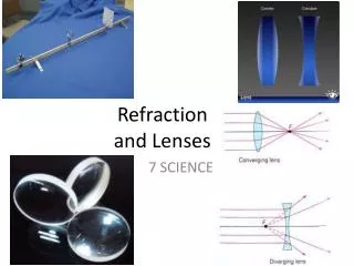
Lenses Snell’s law n1 sina1 = n2 sin a2 Descartes’ law
Paraxial (or first-order) optics Snell’s law: n1 sina1 = n2 sin a2 Small angles: n1a1 n2a2
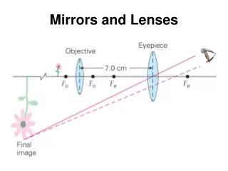
Thin Lenses spherical lens surfaces; incoming light parallel to axis; thickness << radii; same refractive index on both sides
Thin Lenses http://www.phy.ntnu.edu.tw/java/Lens/lens_e.html
yields Similar formula for The depth-of-field
The depth-of-field decreases with d, increases with Z0 strike a balance between incoming light and sharp depth range
Deviations from the lens model 3 assumptions : 1. all rays from a point are focused onto 1 image point 2. all image points in a single plane 3. magnification is constant deviations from this ideal are aberrations
Aberrations 2 types : 1. geometrical 2. chromatic geometrical : small for paraxial rays study through 3rd order optics chromatic : refractive index function of wavelength
Geometrical aberrations • spherical aberration • astigmatism • distortion • coma aberrations are reduced by combining lenses
Spherical aberration rays parallel to the axis do not converge outer portions of the lens yield smaller focal lenghts
Astigmatism Different focal length for inclined rays
Distortion magnification/focal length different for different angles of inclination pincushion (tele-photo) barrel (wide-angle) Can be corrected! (if parameters are know)
Coma point off the axis depicted as comet shaped blob
Chromatic aberration rays of different wavelengths focused in different planes cannot be removed completely sometimes achromatization is achieved for more than 2 wavelengths
Lens materials reference wavelengths : F = 486.13nm d = 587.56nm C = 656.28nm lens characteristics : 1.refractive indexnd 2. Abbe number Vd= (nd- 1) / (nF - nC) typically, both should be high allows small components with sufficient refraction notation : e.g. glass BK7(517642) nd = 1.517 and Vd= 64.2
Lens materials Crown Glass Fused Quartz & Fused Silica Calcium Fluoride 9000 Germanium 14000 18000 Zinc Selenide Saphire 6000 Plastic (PMMA) 100 200 400 600 800 1000 1200 1400 1600 1800 2000 2200 2400 WAVELENGTH (nm) additional considerations : humidity and temperature resistance, weight, price,...
Vignetting Figure from http://www.vanwalree.com/optics/vignetting.html
Photographs (Niepce, “La Table Servie,” 1822) Milestones: Daguerreotypes (1839) Photographic Film (Eastman,1889) Cinema (Lumière Brothers,1895) Color Photography (Lumière Brothers, 1908) Television (Baird, Farnsworth, Zworykin, 1920s) Collection Harlingue-Viollet. CCD Devices (1970) more recently CMOS
Cameras we consider 2 types : 1. CCD 2. CMOS
CCD separate photo sensor at regular positions no scanning charge-coupled devices (CCDs) area CCDs and linear CCDs 2 area architectures : interline transfer and frame transfer photosensitive storage
Foveon 4k x 4k sensor 0.18 process 70M transistors CMOS Same sensor elements as CCD Each photo sensor has its own amplifier More noise (reduced by subtracting ‘black’ image) Lower sensitivity (lower fill rate) Uses standard CMOS technology Allows to put other components on chip ‘Smart’ pixels
Mature technology Specific technology High production cost High power consumption Higher fill rate Blooming Sequential readout Recent technology Standard IC technology Cheap Low power Less sensitive Per pixel amplification Random pixel access Smart pixels On chip integration with other components CCD vs. CMOS
Color cameras We consider 3 concepts: • Prism (with 3 sensors) • Filter mosaic • Filter wheel … and X3
Prism color camera Separate light in 3 beams using dichroic prism Requires 3 sensors & precise alignment Good color separation
Filter mosaic Coat filter directly on sensor Demosaicing (obtain full colour & full resolution image)
Filter wheel Rotate multiple filters in front of lens Allows more than 3 colour bands Only suitable for static scenes
Prism vs. mosaic vs. wheel approach # sensors Separation Cost Framerate Artefacts Bands Prism 3 High High High Low 3 High-end cameras Mosaic 1 Average Low High Aliasing 3 Low-end cameras Wheel 1 Good Average Low Motion 3 or more Scientific applications
new color CMOS sensorFoveon’s X3 smarter pixels better image quality
Reproduced by permission, the American Society of Photogrammetry and Remote Sensing. A.L. Nowicki, “Stereoscopy.” Manual of Photogrammetry, Thompson, Radlinski, and Speert (eds.), third edition, 1966. The Human Eye Helmoltz’s Schematic Eye
The distribution of rods and cones across the retina Reprinted from Foundations of Vision, by B. Wandell, Sinauer Associates, Inc., (1995). 1995 Sinauer Associates, Inc. Rods and cones in the periphery Cones in the fovea Reprinted from Foundations of Vision, by B. Wandell, Sinauer Associates, Inc., (1995). 1995 Sinauer Associates, Inc.