Download
1 / 51
620 likes | 1.14k Vues
The HiSIM Family of Compact-Models for Integrated Devices . H. J. Mattausch , N. Sadachika, M. Miyake, H. Kikuchihara, U. Feldmann, and M. Miura-Mattausch Hiroshima University HiSIM Research Center Research Institute for Nanodevice and Bio Systems

E N D
The HiSIM Family of Compact-Models for Integrated Devices H. J. Mattausch, N. Sadachika, M. Miyake, H. Kikuchihara, U. Feldmann, and M. Miura-Mattausch Hiroshima University HiSIM Research Center Research Institute for Nanodevice and Bio Systems Graduate School for Advanced Sciences of Matter
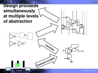
Outline of Presentation • Introduction • Modeling Based on a Consistent Potential Distribution • Bulk MOSFET Model HiSIM2 • Silicon-On-Insulator (SOI) MOSFET • Double-Gate MOSFET • MOS Varactor • High-Voltage Devices • High-Voltage MOSFET • Insulated Gate Bipolar Transistor (IGBT) • Thin-Film Transistor (TFT) • Conclusion
Basic Compact Model Approaches for the MOSFET Threshold-Voltage-Based Models (e. g. BSIM3, BSIM4) • currents expressed as functions of applied voltages • different equations for: • sub-threshold region • linear region • saturation region New Generation of Surface-Potential-Based Models • implicit equation for surface potential • currents determined from drift and diffusion term of current density equation • developed calculation methods for the surface potential: • iterative solution with the exact surface-potential equation ⇒HiSIM • approximate explicit solution by 1st & 2nd order perturbation theory, after prior conditioning of the surface-potential equation ⇒PSP New Generation of Inversion-Charge-Based Models • additional approximation to solve for inversion charge ⇒ EKV, BSIM5, ACM
Basic Equations for Potential-Based Device Model s (solved by SPICE)
Consistency Property of Surface-Potential Model Q(f) = : mobility n = m E: velocity The surface potential consistentlydetermines charges, capacitances and currents under all operating conditions.
Outline of Presentation • Introduction • Modeling Based on a Consistent Potential Distribution • Bulk MOSFET Model HiSIM2 • Silicon-On-Insulator (SOI) MOSFET • Double-Gate MOSFET • MOS Varactor • High-Voltage Devices • High-Voltage MOSFET • Insulated Gate Bipolar Transistor (IGBT) • Thin-Film Transistor (TFT) • Conclusion
Development History of Bulk-MOSFET Model HiSIM • 1990 JJAP Sub-1mm MOSFETs short-channel effect model • 1991 SISPAD “ 1st surface-potential-based model • parameter extraction strategy • ICCAD “ simulation time & stability verification • Siemens Flash-EEPROM concurrent device/circuit development • 1998 STARC 100-nm MOSFET collaboration start Release Activity • 2001 Oct. release to vendors HiSIM1.0.0 source code and manual • 2002 Jan. release to public “ “ • Oct. “ HiSIM1.1.1 “ • 2003 Oct. Test release to STARC clients HiSIM2.0.0 source code and manual • 2005 May release to CMC members HiSIM2.0.0 “ • July “ + Verilog-A code • Oct. “ HiSIM2.2.0 “ • Jan. release to EDA vendors HiSIM2.3.0 • 2007 March “ HiSIM2.4.0 • 2008 Sept. release to CMC members HiSIM2.4.3 eval. for standardization
Modeled Phenomena in HiSIM2.4.3 [Phenomena][Subjects] Short Channel: Reverse-short Channel:impurity pile-up pocket implant Poly-Depletion: Quantum-Mechanical: Channel-Length Modulation: Narrow-Channel: Temperature Dependency:thermal voltage bandgap ni phonon scattering maximum velocity Mobility Models:universal high Field Shallow-Trench Isolation:threshold voltage mobility leakage current Capacitances:intrinsic overlap lateral-field induced fringing [Phenomena][Subjects] Non-Quasi-Static: transient time-domain AC frequency-domain Noise:1/f thermal induced gate cross-correlation Leakage Currents: substrate current gate current GIDL current Source/Drain Resistances: Junction Diode: currents capacitances Binning Option DFM Option
HiSIM’s Surface Potentials at Source and Drain Basic Surface-Potential Equation Iterative HiSIM Solution in Comparison to 2D-Devices Simulation The absolute values of the HiSIM surface potential compare well with 2D simulation.
Surface-Potential Dependence on Applied Voltages fSLsaturates
Bias Dependence & Derivatives of Surface Potential HiSIM accurately reproduces even the bias dependence of the surface-potential derivatives.
Gummel-Symmetry Properties (HiSIM243) model parameters: default Ids / Vx vs. Vx Ids vs. Vx Ids3 / Vx3 vs. Vx Ids2 / Vx2 vs. Vx
Short-Channel-Effect Model (approximating a quadratic potential distribution) M. Miura-Mattausch et al., IEEE TED, 48, p. 2449, 2001.
Pocket-Implantation Model Vth (V) Including tail for high pocket- doping concentrations. H. Ueno et al., IEEE TED, 49, p. 1783, 2002.
Wg/Lg=2mm/40nm Wg/Lg=2mm/200nm Measurement HiSIM Model Extraction for Advanced 45nm Technology HiSIM can model advanced 45nm technology very accurately without the necessity of binning.
Measurement Wg/Lg= 2mm/40nm HiSIM Current Derivatives for Advanced 45nm Technology The current derivatives of a 45nm technology can likewise be well reproduced with HiSIM.
total CPU extrinsic device characteristics Arbitrary Units intrinsic device characteristics fSLiteration fS0 iteration Vgs Data: HiSIM2.4.0 HiSIM’s Model Evaluation Time Iteration for surface-potential determination requires only a small fraction of the total model evaluation time.
Outline of Presentation • Introduction • Modeling Based on a Consistent Potential Distribution • Bulk MOSFET Model HiSIM2 • Silicon-On-Insulator (SOI) MOSFET • Double-Gate MOSFET • MOS Varactor • High-Voltage Devices • High-Voltage MOSFET • Insulated Gate Bipolar Transistor (IGBT) • Thin-Film Transistor (TFT) • Conclusion
BOX FOX 2D-Device Determination of Involved Potentials
I-V Curve Reproduction and Short-Channel Effect This Device does not show a floating body effect!
Comparison with 1/f-Noise in Bulk MOSFETs 1/f-Noise in the SOI-MOSFET is substantially increased!
Modeling of the Floating-Body Effect The floating-body effect is modeled on the basis of excess hole charge due to impact ionization.
Modeling of the Dynamic-Depletion Effect The dynamic-depletion effect is accurately captured due to the consistently potential-based model concept.
Outline of Presentation • Introduction • Modeling Based on a Consistent Potential Distribution • Bulk MOSFET Model HiSIM2 • Silicon-On-Insulator (SOI) MOSFET • Double-Gate MOSFET • MOS Varactor • High-Voltage Devices • High-Voltage MOSFET • Insulated Gate Bipolar Transistor (IGBT) • Thin-Film Transistor (TFT) • Conclusion
Specific Features of the Double-Gate (DG) MOSFET Tsi carrier concentration Vgs=1V Vds=0V gate Tsi=10nm gate Tsi=20nm gate gate Tsi=40nm gate gate Body potential is floating. Tsi The floating body potential makes modeling difficult.
HiSIM-DG Accuracy for the Center Surface Potential The potentials at center and surface are determined with HiSIM-DG as accurately as in 2D-device simulation.
Short-Channel Effect in DG MOSFETs The drastic reduction of the short-channel effect is a big advantage of the double-gate MOSFET.
TSi Nsub fs0 (V) fs0 (V) Potential Dependence: Silicon Thickness and Nsub
C-V Characteristics Reproduction Reduction of Tsi has only a small influence on the capacitance.
TSI=10nm, Tox=1nm, Lg=1um, Vds=50mV Impurity-Concentration Dependence of Vth Influence of Qb cannot be ignored.
Outline of Presentation • Introduction • Modeling Based on a Consistent Potential Distribution • Bulk MOSFET Model HiSIM2 • Silicon-On-Insulator (SOI) MOSFET • Double-Gate MOSFET • MOS Varactor • High-Voltage Devices • High-Voltage MOSFET • Insulated Gate Bipolar Transistor (IGBT) • Thin-Film Transistor (TFT) • Conclusion
Carrier-Movement Delay in Accumulation Mode t is inverse proportional to the electric field.
Outline of Presentation • Introduction • Modeling Based on a Consistent Potential Distribution • Bulk MOSFET Model HiSIM2 • Silicon-On-Insulator (SOI) MOSFET • Double-Gate MOSFET • MOS Varactor • High-Voltage Devices • High-Voltage MOSFET • Insulated Gate Bipolar Transistor (IGBT) • Thin-Film Transistor (TFT) • Conclusion
(Asymmetric) (Symmetric) High-Voltage MOSFET Structures Public/Release Activities for HiSIM_HV Model 2006 Oct. candidate for CMC standardization 2007 Dec. selected for CMC standardization 2008 June HiSIM_HV1.0.2release (evaluated as first standard version) 2008 Dec. HiSIM_HV1.0.2 named CMC standard model
Complete Surface-Potential-Based Model HiSIM for Bulk-MOSFET fS0 : at source edge fSL : at the end of the gradual-channel approx. fS(DL) : at drain edge (calculated from fSL) Beyond Gradual-Channel Approximation • Channel-Length Modulation • Overlap Capacitance HiSIM2Properties Facilitating Extension to HV-MOS
Ldrift Consistent Potential Drop Modeling in Drift Region Ndrift Potential drop in the drift region All important potential values are known. No sub-circuit for the potential drop is necessary.
fS(DL)[V] fS(DL)[V] fS(DL) fS(DL)[V] fS(DL)[V] HV HV : potential determining LDMOS characteristics fS(DL) Vds[V] Vgs[V] Consistency Evaluation of Key Potential Values HiSIM reproduces fS(DL) calculated by 2D-device simulator.
: 2D-Device Simulation Results : HiSIM-HV Results Vds=20V gm [S] Vds=10V Id [A] Vds=5V Vds=0.1V Accuracy Comparison of Id-Vgs Good agreement between HiSIM-HV results and 2D-device simulation results is achieved.
: 2D-Device Simulation Results : HiSIM-HV Results Vgs=10V Vgs=7.5V Id [A] gd [S] Vgs=5V Vgs=2.5V Accuracy Comparison of Id-Vds Quasi-saturation behavior of LDMOS is reproduced.
HV Reproduction of Key Capacitance Features Ldrift = 1.5mm Vds = 10V Vgs [V] Vgs [V] Charge in the drift region is modeled explicitly.
2.0 Cgg 1.8 Cgd 1.2 Capacitance [fF] Capacitance [fF] Cgb 0.8 Cgs Vds=0V 0.4 -4 -2 0 2 4 Vgs [V] Vgs [V] Reproduction of Intrinsic Capacitances Asymmetrical LDMOS Symmetrical HVMOS HiSIM-HV is capable to reproduce all intrinsic capacitances with good accuracy.
Concept of the HiSIM-IGBT Compact Model Schematic structure of a modern trench-IGBT Jn n- (base) Simplified circuit diagram of the HiSIM-IGBT model Consistent potential extension in HiSIM-IGBT is achieved by calculation based on Kirchhoff’s laws.
Fitting Results for the I-V Characteristics of the IGBT HiSIM-IGBT achieves accurate reproduction of the IGBT’s I-V characteristic and also scales with the base doping. M. Miyake et al., “A Consistently Potential Distribution Oriented Compact IGBT Model”, IEEE PESC, pp. 998-1003, June 2008
Outline of Presentation • Introduction • Modeling Based on a Consistent Potential Distribution • Bulk MOSFET Model HiSIM2 • Silicon-On-Insulator (SOI) MOSFET • Double-Gate MOSFET • MOS Varactor • High-Voltage Devices • High-Voltage MOSFET • Insulated Gate Bipolar Transistor (IGBT) • Thin-Film Transistor (TFT) • Conclusion
Concept of the Thin-Film-Transistor (TFT) Model Typical structure of the poly-Si TFT Effect of Traps on the I-V characteristic TFT modeling is based on including the trap charge in the Poisson equation. S. Miyano et al., “A surface potential based Poly-TFT model for circuit simulation”, IEEE SISPAD, Sept. 2008
Reproduction of Fabricated TFT-Device Data Accurate reproduction of I-V characteristic and scaling with gate length is achieved. S. Miyano et al., “A surface potential based Poly-TFT model for circuit simulation”, IEEE SISPAD, Sept. 2008