Download

1 / 15
150 likes | 242 Vues
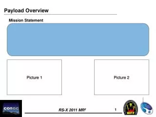
SUMARE PAYLOAD. CONTENTS Objectives. Sensors choice. Sensors performances. Implant possibilities. Sensors conditioning. Schedule. Sensors integration drawings. Fins navigation trials. Fresh water tank measurement sensors. 2. OBJECTIVES

E N D
CONTENTS • Objectives. • Sensors choice. • Sensors performances. • Implant possibilities. • Sensors conditioning. • Schedule. • Sensors integration drawings. • Fins navigation trials. • Fresh water tank measurement sensors. 2
OBJECTIVES The “Payload” will assume two main operational functions. • Monitoring of the volumetric evolution of sand banks. • Obstacles avoidance. 3
SENSORS CHOICE Altimeter. Acoustic high frequency transducer ( Resolution) Obstacles avoidance. The inner Mauve transducer is not available (Software limits / Discrimination). The transducer is the same than for altimeter. 4
SENSORS PERFORMANCES Measurement limit : 50 m Measurement mode : Free run Measurement speed : 10 Hz Power supply : 12 or 24 VDC Interface : RS 232 or RS 485 Frequency : 500 kHz Conical beam : 6° 5
IMPLANT POSSIBILITIES 1 : Risk on Payload structure (depth) Obstacle avoidance sensor not possible. 2 : Risk on launching. 3 : chosen solution 6
SENSORS CONDITIONING Conditioning electronic : two output Two output are available on MMNS 1 RS 232 1 RS 485 The two electronic signal conditioning units will be connected on these outputs 7
SCHEDULE 8
SENSORS INTEGRATION. 4 configurations will be tested at sea. • 1 :Fins 60 mm long in front of the payload. • 2 :Fins 60 mm long in back of the payload. • 3 :Fins 120 mm long in front of the payload. • 4 :Fins 120 mm long in back of the payload. 9
FRESH WATER TANK MEASUREMENT SENSORS 15