Download
1 / 39
400 likes | 633 Vues
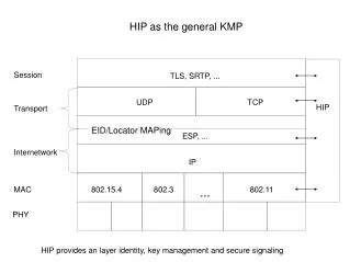
802.11 FHSS PHY Specification. Contents. Frequency Hopping Specifications Physical Layer architecture Physical Layer Convergence Procedure (PLCP) Interactions between MAC, PLCP and PMD PHY procedures: Clear Channel Assessment Transmit Receive Management. MAC Layer. PHY Layer.

E N D
Contents • Frequency Hopping Specifications • Physical Layer architecture • Physical Layer Convergence Procedure (PLCP) • Interactions between MAC, PLCP and PMD • PHY procedures: • Clear Channel Assessment • Transmit • Receive • Management 2
MAC Layer PHY Layer 2.4 GHz FHSS 1 Mbps 2 Mbps 2.4 GHz DSSS 1 Mbps 2 Mbps Infrared IR 1 Mbps 2 Mbps 2.4 GHz DSSS 5.5 Mbps 11 Mbps 5 GHz OFDM 6, 9, 12, 18, 24, 36, 48, 54 Mbps IEEE 802.11b IEEE 802.11a IEEE 802.11 Where does FHSS fit in the 802.11 Architecture? 3
802.11 FHSS PHY Overview • 2.4 GHz ISM band • 1 Mbps data rate (GFSK modulation) • 2 Mbps data rate (4-level GFSK) (optional) • 79 nonoverlapped frequency channels in North America and Europe 23 nonoverlapped frequency channels in Japan • Center frequencies of adjacent channels are separated by 1 MHz • Up to 26 collocated networks can operate (N. America/Europe) with minimal interference 5
Channel Frequencies • In N. America, there are 79 channels • The center frequencies for adjacent channels are spaced 1MHz apart: 8
Hop Sequences (N. America) • The 802.11 standard specifies a base sequence: • The channel number for the ith hop is given by [b(i) + 2] • Additional patterns are formed by adding k to each channel in the base sequence • i.e. the ith hop in sequence k is given by [b(i) + k] mod 79 + 2 • Each sequence uses all 79 channels 9
Hop Sequence - example • The channel numbers in the base sequence are: • [b(i) + 2] • {2, 25, 64, 10, 45, 18, 27, … , 32, 48} • Center frequencies (in GHz) are: {2.402, 2.425, 2.464, 2.410, …} • The channel numbers in sequence 10 are : • {[b(i) + 10] mod 79} + 2 • {12, 35, 74, 20, 55, 28, 37, … , 42, 58} • Center frequencies (in GHz) are {2.412, 2.435, 2.474, 2.420, …} 10
Hop Sequence - Properties • The sequences are divided into 3 sets of 26 sequences. • Co-located networks using different sequences from the same set, will experience minimum collisions • Frequency hopping sequences are designed so that consecutive hops are at least 6 MHz apart 11
Modulation • 802.11 FHSS PHY uses Frequency Shift Keying • Different values (0 or 1) are represented by different frequencies • In order to minimize (wasted) power, transmitted outside of the channel, transitions between frequencies are smoothed • The way 802.11 FHSS does this is known as Gaussian Frequency Shift Keying (GFSK) • This modulation gives a data rate of 1MB/s 12
Modulation for 2Mb/s • 802.11 FHSS PHY specifies an optional2Mbps modulation scheme • This uses 4-level GFSK, where two data bits are ‘carried’ in each symbol : 13
Further FHSS Specifications • Slot time (MAC layer) 50 s • SIFS time (MAC layer) 28 s • Hop time (i.e. time taken to change frequency) 224 s • Maximum dwell time (N. America) 400 ms • Maximum output power • 1000 mW USA • 100 mW Europe • 10 mW/MHz Japan • Minimum transmitted power 10 mW • Receiver sensitivity -80 dBm @ 0.03 FER (400 bytes) • Rx adjacent channel rejection > 30 dB @ 4 MHz (and 8 MHz) separation between channels 14
Protocol Architecture and the Physical Layer Convergence Procedure (PLCP) 15
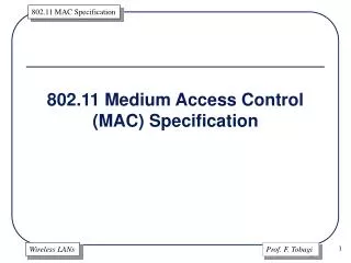
PLCP Sublayer PLME PHY Layer PMD Sublayer PHY layer architecture • Physical Medium Dependent (PMD)sublayer: provides a mean to send and receive bits between stations through the wireless medium • Physical Layer Convergence Procedure (PLCP): maps the MAC PDU (MPDU) into a framing format suitable for transmission; this function simplifies the PHY service interface to the MAC services • Physical Layer Management Entity (PLME): performs management of the local PHY functions 16
Need for the PLCP (1) • PHY layer (PMD) is only concerned with transmitting bits • MAC layer is only concerned with MAC frames • Need function between PHY and MAC to achieve the following: • Allow receiver to acquire bit-synchronization (since PHY is not synchronous) • Indicate to the receiver the start and end of a MAC frame • Indicate the data rate (modulation) used • Carry out functions which are PMD-dependent but which act only on certain parts of the frame (e.g. scrambling) • Physical Layer Convergence Procedure does the above 17
Need for the PLCP (2) • The PLCP makes the MAC-PHY interface independent of the Physical Layer used • i.e. the same MAC can be used for many different Physical layer protocols • This makes the MAC layer much more simple! 18
FHSS PLCP preamble(12 octets) FHSS PLCP header(4 octets) Whitened PSDU PLCP Frame Format PLW: PSDU Length Word PSDU: PLCP Service Data Unit PSF: PLCP Signaling Field CRC: Cyclic Redundancy Check 1 Mbps transmission 1 (or 2 Mbps) transmission Synchronization (80 bits) Start Frame Delimiter (16 bits) PSF (4 bits) CRC (16 bits) PLW (12 bits) 19
Fields in the PLCP Frame (1) • Synchronization: 80-bit field containing an alternating 01 pattern; used for signal detection, antenna selection, frequency offset compensation and synchronization • Start Frame Delimiter (SFD): 0000 1100 1011 1101; used for frame timing • PSDU Length Word (PLW): The number of octets contained in the PSDU (up to 4095 octets); used for the end of frame detection • CRC: CCITT CRC-16 FCS; used to protect PLW and PSF 20
Fields in the PLCP Frame (2) • PLCP Signaling Field (PSF): Data rate indication of the whitened PSDU • 1 Mbps is the only mandatory data rate up to now; the first bit is reserved for future use (set to 0) and the three other bits follow this table 21
PSDU ‘Whitening’ • Data whitener: It uses a 127-bit frame-synchronous scrambler followed by a 32/33 bias-suppression encoding • This is done to: • Randomize the data • Minimize the data DC bias • Minimize maximum run lengths 22
Management Functions • The MAC Layer Management Entity(MLME) and PHY Layer Management Entity (PLME) contain attributes, processes, etc. necessary for the operation of the MAC and PHY layers respectively • Attributes are contained in a conceptual database called the Management Information Base(MIB) 27
Management - example • The MLME is responsible for the Frequency Hopping time synchronization, which ensures that all stations are hopping at the same time • The MLME will update the PLME using PLME-SET primitives to update the current hop set, current hop pattern, and current index in the MIB • The PLCP acts immediately on these updates (e.g. changing frequency) • Note: Unlike the MAC, the MLME is not entirely PHY-independent 28
PHY layer functions Clear Channel Assessment Transmit Receive 30
PLCP State Machine • *** 31
Clear Channel Assessment • As we will see, the MAC protocol is based on a Carrier Sense mechanism • In order to support this, the PHY layer must provide an indication to the MAC layer of the state of the channel • Clear Channel Assessment (CCA) is the PHY-layer process which provides idle/busy information to the MAC layer 32
PLCP Transmit Procedure (1) • PLCP switches PMD to transmit mode after receiving PHY.TXSTART.request with the total number of octets and the data rate from the MAC layer • PMD responds by sending the preamble at the antenna within 20 s • Transmitter sends preamble and header at 1 Mbps and then changes to the data rate specified in the request to send the PSDU • After completion of the transmission PLCP sends a PHY-TXEND.confirm to MAC • PHY shuts off the transmitter and switched PMD to receive mode 34
PLCP Receive procedure (1) • PMD will indicate a busy medium when it senses a signal having a power level of at least -85 dBm • When CCA discovers a busy medium and the valid preamble of an incoming frame, PLCP monitors the frame header • If PLCP finds the header is error-free, it will send a PHY-RXSTART.indicate to MAC along with the information in the header • PLCP sets a counter to keep track of the number of octets received so that PLCP will know the end of the frame • As PLCP receives data, it sends PHY-DATA.indicate to MAC • PLCP sends a PHY-RXEND.indicate to MAC when its counter indicates the end of the frame 37