Download
1 / 36
360 likes | 451 Vues
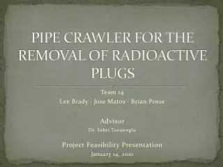
Peristaltic Crawler for the Removal of Radioactive Plugs. Presented by: Lee Brady DOE Fellow. Overview . Problem Statement Motivation Proposed Solution Design Metrics Mechanical Designs Vs. Pneumatic Design Prototype Characterizing Sludge Final Design Fault Tolerant

E N D
Peristaltic Crawler for the Removal of Radioactive Plugs Presented by: Lee Brady DOE Fellow
Overview • Problem Statement • Motivation • Proposed Solution • Design Metrics • Mechanical Designs Vs. Pneumatic Design • Prototype • Characterizing Sludge • Final Design • Fault Tolerant • Modeling and Engineering Analysis • Force Analysis • Tether Length? • Environmental Impact • Future Work • Acknowledgements
Problem Statement • The Manhattan Project left behind an estimated 55 million gallons of radioactive waste in Hanford, WA • 69 of 149 single-shell tanks have begun to leak • Complete transfer into secure double-shell tanks is required by 2040 • Delays due to blockages in transfer pipelines delay the process further • Increasing costs • Threatening the Environment
Motivation • Radioactive materials can reach the Columbia River in as little as 3 years • 270 billion gallons of contaminated soil and ground water in neighboring aquifers • Previously tested unplugging technologies failed to achieved satisfying results • Unplugging capabilities drastically reduce as the distance to the plug increases
Proposed Solution • A crawler that will crawl to the plug and apply abrasive techniques to remove the plugs • Thus reducing the distance to the plug
Design Metrics • Based on Hanford pipelines the crawler and components must: • Fit in a pipe having inner diameter of 3” • Negotiate through 90˚ bends w/ turning radius of 4.25” • Be able to pull its own weight including weight of tether. • Never exceed 300 psi • Be radiation resistant for a10 Gy/hr environment • Be capable of removing clogs that exist in pipelines
Prototype Construction • 6061 Aluminum • 1.5” Hoover Vacuum Hose • 2” Black Duct Hose • Spiral Hose • Boot Clamps • Inner Tubes • Pressure Nozzle Bracket
Characterizing Sludge • Simulants can be grouped into three major categories: • sludge simulants (most prominent) • hardpan waste simulants • saltcake waste simulants • The Pacific Northwest National Laboratory has extensive documentation on different waste simulants • Non-hazardous to the environment • Formulated to resemble the physical properties of radioactive plugs that occur in the pipelines • The mechanical strength, porosity, dissolution rate, solubility and thermal conductivity of the simulant are studied by DOE scientists. • Due to availability, Bentonite Clay, a sludge type simulant was used for testing of the crawler’s unplugging tool.
Final CrawlerDesign of Bodies • 516 Stainless Steel Bodies
Final CrawlerDesign of Bellows • 516 Stainless Steel custom made, edge welded bellow • Duraflex, Inc • 8:1 collapse ratio
Fault Tolerant Design • Inner Tube Ruptures • Crawler Jamming • Inner/Outer Bellow Ruptures • Rim Separation
Cost Analysis Labor Costs
Camera • According to ThermoFisher Company, a commercial charge couple device(CCD) camera could last one hour at 300 Gy/hr. (Hanford = 10 Gy/hr)
Camera • The exact life of a CCD camera in a 10Gy/hour environment is unknown. • However, another radiation hardened inspection device can survey where the blockage is in the pipeline. • After, the peristaltic crawler can be sent in once the location and distance of the plug is known.
Stress on Inner Tubes • Polyurethane 5511 PSI Ultimate Stress
Tether Length? • 300 PSI bellow = 345 lbs of pulling force • 100 ft of final tether ~ 15 lbs • Four 1/16” and One 1/8” pneumatic tubes • One .48” OD Hydraulic Hose • One1/16” S.S winch cable • 345 lbs = 2300 feet (neglecting friction) • 2300 feet is improbable • Due to frictional forces inside the pipeline and how the 90 degree elbows affect the force required to pull the tether. • More feasible for unplugging the pipes in treatment facilities • Few hundred feet
Anchoring Force • To preserve the realistic integrity of the parts and mathematical stability of the model thickness equates to .38 inches.
Stress AnalysisInitial Tool Support, 50 lb load, 0.05 in. Mesh Size
Stress AnalysisFinal Tool Support, 350 lb Load, .05 in. Mesh Size
Environmental Impact • While the crawler is in a vacuum stage it is possible that it may pull contaminated air out into the atmosphere. • An air filter used in the nuclear industry will prevent contaminated air from expelling into the environment • The crawler and tether will be radioactive the instant it is introduced to the pipeline. • To prevent the contamination of objects outside the pipeline, the crawler will be contained in a lead housing with a reeling system • The crawler will be stored inside this unit and removed from the site safely.
Future Work • The successful removal of a plug is based on two things: • Tool Effectiveness • Sufficient Path for Removed Debris travel to the rear of the crawler • A hydraulic pressure nozzle was used in the project but may not be the most effective tool against certain types of plugs. • Implementation of a mechanical type abrasive tool. • Can be powered by hydraulics as to avoid the use of circuitry.
Future Work • Four-piston type mechanism mounted on the perimeter of the front rim, the nozzle will be able to adjust the aim of the trajectory of the nozzle plume. • By using pneumatics the individual pistons can be adjusted to aim the crawler head left, right, up or down. • The four-piston feature may also improve the maneuverability of the crawler.
Conclusion • Peristaltic Crawler was designed under all the design metrics • Versatile platform that can implement more powerful unplugging tools • Simple, Robust and Fault Tolerant
Acknowledgements • ARC Faculty • Leonel Lagos, Ph.D, PMP • Tomas Pribanic, MS • Dwayne McDaniel, Ph.D, PE • Seckin Gokaltun, Ph.D • Amer Awwad, PE • Prof. Rick Zicarelli • Engineering Colleagues