Download
1 / 25
260 likes | 413 Vues
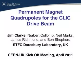
Novel Tunable Permanent Magnet Quadrupoles for the CLIC Drive Beam. Ben Shepherd , Jim Clarke, Norbert Collomb , Graham Stokes STFC Daresbury Laboratory, UK Antonio Bartalesi, Michele Modena, and Mike Struik CERN, Geneva, Switzerland CLIC Workshop 2014 CERN, 3-7 February 2014.

E N D
Novel Tunable Permanent Magnet Quadrupoles for the CLIC Drive Beam Ben Shepherd, Jim Clarke, Norbert Collomb, Graham StokesSTFC Daresbury Laboratory, UK Antonio Bartalesi, Michele Modena, and Mike StruikCERN, Geneva, Switzerland CLIC Workshop 2014 CERN, 3-7 February 2014 Artwork: S. Kimball
The CLIC Drive Beam • The drive beam decelerates from 2.4 GeV to 0.24 GeV transferring energy to the main beam • As the electrons decelerate, quadrupoles are needed every 1m to keep the beam focused • The quadrupole strengths scale with the beam energy • The CLIC accelerator length is ~42km so there are ~42,000 quadrupoles needed
Quadrupole Tunability • The nominal maximum integrated gradient is 12.2T and the minimum is 1.22T • For operational flexibility each individual quadrupole must operate over a wide tuning range • 70% to 120% at high energy (2.4 GeV) • 7% to 40% at low energy (0.24 GeV) 12.2 T 1.22 T
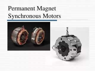
Permanent Magnet Option • The integrated magnet strength requirement is very challenging (given the space constraints) for a conventional electromagnet • The nominal power consumption for the EM version will be ~8 MW in nominal mode and up to ~17 MW in tune-up mode • Total Power Load limit to air within the tunnel is only 150 W/m (all components) • A PM quad would potentially have many advantages • Vastly reduced electrical power • Very low operating costs • No cooling water needs • Very low power to air • We have been investigating the PM option for the drive beam
Permanent Magnet Challenges • There are many existing PM quadrupole examples • The combination of high strength, large tunability, high field quality, and restricted volume meant that a new design was required • Additional challenges for PM include possible radiation damage, field variation with temperature, PM strength variation from block to block (material and engineering tolerances) • The complete tuning range (120% to 7%) could not be met by a single design • We have broken the problem down into two magnet designs – one high energy and one low energy
Quadrupole Types Erik Adli & Daniel Siemaszko Low Energy Quad High Energy Quad • High energy quad – Gradient very high • Low energy quad – Very large dynamic range
High Energy Quad Design • NdFeB magnets with Br = 1.37 T (VACODYM 764 TP) • 4 permanent magnet blocks each 18 x 100 x 230 mm • Mounted at optimum angle of 40° • Max gradient = 60.4 T/m (stroke = 0 mm) • Min gradient = 15.0 T/m(stroke = 64 mm) • Pole gap = 27.2 mm • Field quality = ±0.1% over 23 mm Stroke = 64 mm Poles are permanently fixed in place Stroke = 0 mm
Engineering of High Energy Quad • Single axis motion with one motor and two ballscrews • Two linear encoders to check position on both sides with 1mm accuracy • Maximum force is 16.4 kN per side, reduces by x10 when stroke = 64 mm • PM blocks bonded to steel bridge piece and protective steel plate also bonded • Steel straps added as extra security
PM Quads in CLIC Very tight space constraints Norbert Collomb
Magnet Centre Movement • The magnet centre moves upwards by ~100 µm as the permanent magnets are moved away • 3D modelling suggests this is due to the rails being ferromagnetic (µr~ 100, measured) and not mounted symmetrically about the midplane – should be easy to fix • Motor/gearbox assembly may also be a contributing factor
Low Energy Quad Design • Lower strength easier but requires much larger tunability range (x10) • Outer shell short circuits magnetic flux to reduce quad strength rapidly • NdFeB magnets with Br= 1.37 T (VACODYM 764 TP) • 2 permanent magnet blocks are 37.2 x 70 x 190 mm • Max gradient = 43.4 T/m (stroke = 0 mm) • Min gradient = 3.5 T/m (stroke = 75 mm) • Pole gap = 27.6 mm • Field quality = ±0.1% over 23 mm Stroke = 75 mm Poles and outer shell are permanently fixed in place. Stroke = 0 mm
Engineering of Low Energy Quad • Simplified single axis motion with one motor and one ballscrew • Two linear encoders to check position on both sides with 1mm accuracy • Maximum force is only 0.7 kN per side • PM blocks bonded within aluminium support frame
Assembly at Daresbury Poles PM block in frame Outer shell Assembly of poles Lowering into measurement rig Insertion of PMs PMs inserted Motor added Outer shell added
Next: PM dipoles • STFC-CERN work package from April 2014: investigate PM dipoles for: • Drive Beam Turn Around Loop (DB TAL) • Main Beam Ring to Main Linac (MB RTML) • Total power consumed by both types: 15 MW • Reduced-length DB TAL prototype to be constructed by Dec 2015
Summary • The CLIC Drive Beam quadrupoles are rather challenging magnets because of their high strength and tight space constraints • PM driven quads have many advantages in terms of operating costs, infrastructure requirements, and power load in the tunnel • We have shown that only two PM designs are required to cover the entire range of gradients required • The high energy quad has been prototyped and measured and found to successfully generate the expected integrated gradient • The magnetic centre moves vertically as the gradient is adjusted and modelling suggests this is due to non-symmetric ferromagnetic rails • Further tests will be made to confirm this • The low energy quad has been designed and assembly of the prototype is almost complete at Daresbury • It will undergo a similar set of magnetic tests at Daresbury and then CERN
Acknowledgments • Daresbury Laboratory team • Magnet design: Ben Shepherd, Jim Clarke, Neil Marks • Mechanical design: Norbert Collomb, James Richmond, Graham Stokes • CERN team • Project lead: Michele Modena • Magnet measurements: Antonio Bartalesi, Mike Struik, Marco Buzio, Samira Kasaei • Supporting cast: Alexandre Samochkine, Dmitry Gudkov, Evgeny Solodko, Alexander Aloev, Alexey Vorozhtsov, Guido Sterbini
Thanks for your attention! Artwork: J. Flesher