Download
1 / 14
150 likes | 332 Vues
TCP Throughput Testing Methodology IETF 77 Anaheim Barry Constantine barry.constantine@jdsu.com Reinhard Schrage rschrage@schrageconsult.net. 7. Application. 6. Presentation. 5. Session. 3. Network. 2. Datalink. 1. Physical. OSI Model: Division of Responsibility. IT department

E N D
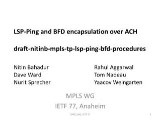
TCP Throughput Testing Methodology IETF 77 Anaheim Barry Constantine barry.constantine@jdsu.com Reinhard Schrage rschrage@schrageconsult.net
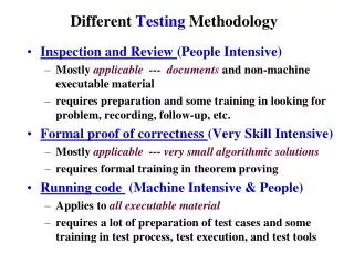
7 Application 6 Presentation 5 Session 3 Network 2 Datalink 1 Physical OSI Model: Division of Responsibility IT department responsibility HTTP, FTP, Email, etc. Shared responsibility TCP 4 Transport IP Network Provider’s responsibility Ethernet
History: Provisioning of Managed Networks • Even though RFC2544 was originally intended to benchmark network equipment in a lab environment, network providers have used it to benchmark operational networks in order to provide Service Level Agreements (SLAs) to their business customers • It is difficult if not impossible, to extrapolate end-user application layer performance from RFC2544 results and the goal of RFC2544 was never intended to do so. • Network providers are coming to the realization that RFC2544 testing and TCP layer testing are required to more adequately ensure end-user satisfaction
Network Provisioning– RFC 2544 Overview • Goal • Run a sequence of Layer 2 / 3 tests to verify the general performance of a circuit prior to “turning on” the end user service • Test method • Packet based end-end or looped-back • Test end-end network: • Throughput rate in frames/sec or % link utilization • Frame loss absolute or % • Delay/Latency in ms or us • Back-to-Back in frames or time • Test parameters: • Packet size: 64, 128, 256, 512, 1024, 1280, 1518 bytes • Packet rate: 10, 20, 30, 40, 50, 60, 70, 80, 90, 100% of maximum rate • Burst: Time or number of packets
4 3 2 1 The Challenge of Measuring TCP Throughput cwnd = current TCP estimation of available capacity in the network High ssthresh TCP Window halving upon loss RTO Timer expiration Adjusted ssthresh cwnd=1 upon timeout Congestion Avoidance cwnd Slow Start Slow Start Fast Retransmission Time • The predicted Bulk Transport Capacity (BTC) occurs during the peak of the Congestion Avoidance phase • In the draft, we call this the “maximum sustained TCP throughput”
TCP Test Methodology Overview “0”.Run traditional RFC2544 to verify the integrity of the network before conducting TCP testing. • Path MTU Detection (per RFC4821) • Verify network MTU with active TCP segment size testing • Baseline Round-trip Delay and Bandwidth • Predict optimum TCP window size • Single TCP Connection Throughput Tests • Verify TCP window size predictions • MSS Throughput Tests • Verify expected throughout per various MSS sizes • Multiple TCP Connection Throughput Tests • Test for tail drop condition (default FIFO queuing), policing, etc. • TCP + Background UDP Prioritization Tests • Verify end-end network prioritization with stateful TCP traffic (multiple TCP connections)
Step 1: Path MTU Detection (per RFC4821) Verify network MTU with active TCP MSS testing using Packetization Layer Path MTU Discovery (PLPMTUD) PLPMTUD is an extension to existing Path MTU Discovery methods described in RFC1191 and RFC1981 PLPMTUD uses TCP instead of ICMP to probe the network and discover the minimum MTU size supported When ICMP messages are not supported by network devices, traditional PMTUD fails to properly identify the minimum MTU The minimum MTU from this step is used as the basis for the MSS in subsequent tests
Step 2: Baseline Round-trip Time and Bandwidth Round-trip Time and Bandwidth capacity measurements provide estimates of the ideal TCP window size, which will be used in subsequent test steps. These latency and bandwidth tests should be run long enough to characterize the performance of the network over the course of a meaningful time period. The test tool must be capable of delivering the TCP capacity (PC tools for certain speeds, dedicated test tools for higher speeds such as 1G/10GigE) Round Trip Time TCP In-flight Data
Bandwidth Measurement Interval Considerations Bandwidth measurements can look very differently if the procedure to perform measurements is not clearly defined Compare display of measurements of below simple network if done with different epoch intervals
Step 3: Single TCP Connection Throughput Tests With baseline measurements of round trip time and bandwidth, a series of single connection TCP throughput tests can be conducted to baseline the performance of the network against expectations Provide chart of throughput, retransmissions, RTT over time and the concept of a “TCP Goodput” type metric Provide table of “input” versus expected “output” guideline And provide the formula(s) used to derive the TCP “output” guideline This is the BDP calculation with provisions for MSS size and L2+L3+L4 overhead
Step 4: MSS Throughput Tests By varying the MSS size of the TCP connection(s), the ability of the network to sustain expected TCP throughput can be verified. Similar to RFC2544 packet size tests, which determine a routing or switching device’s ability to handle loads in term of packets per second
Step 5: Multiple TCP Connection Throughput Tests Default router queuing (i.e. FIFO based) is inefficient for business critical applications. Can cause TCP Tail Drop and Global Synchronization; from the user’s perspective, this condition causes significant performance degradation By automating end-to-end testing with several (4 or more) simultaneous TCP sessions, detect non-optimized shaping / queuing in the network i.e. an over-utilized link should employ a random early discard technique to avoid tail drop 45 Mb/sec Link, RED Queuing 45 Mb/sec Link, FIFO Queuing (Tail Drop)
Step 6: TCP + Background UDP Prioritization Tests Application traffic such as Citrix, Peoplesoft, etc. now require real-time performance to meet end-user response time expectations; there is a fine balance between application data traffic prioritization and VoIP, Video, etc. Emulate bursty TCP traffic sessions (i.e. Citrix, HTTP, SMTP, etc.) with the proper CoS and QoS values at an average throughput rate and with peaks. Emulate concurrent UDP sessions (i.e. VoIP G.711) with the proper CoS and QoS values TCP Session #1
Next Steps for the TCP Testing Draft • Work with network providers to solicit feedback and to better align the testing methodology with practical application “in the field” • Define the “TCP Goodput” metric in the draft and provide recommended thresholds in various network topologies (metro fiber, DSL access, cable access, satellite, etc.) • Develop the MSS Throughput and Multiple Connection test sections to the next level of detail