Download
1 / 57
570 likes | 715 Vues
LAN (Ethernet), Multicast. Why Multicast. When sending same data to multiple receivers better bandwidth utilization less host/router processing quicker participation Application Video/Audio broadcast (One sender) Video conferencing (Many senders) Real time news distribution

E N D
Why Multicast • When sending same data to multiple receivers • better bandwidth utilization • less host/router processing • quicker participation • Application • Video/Audio broadcast (One sender) • Video conferencing (Many senders) • Real time news distribution • Interactive gaming • Cluster computing
IP multicast service model • Invented by Steve Deering (PhD. 1991) • It’s a different way of routing datagrams • RFC1112 : Host Extensions for IP Multicasting - 1989 • Senders transmit IP datagrams to a "host group" • “Host group” identified by a class D IP address • Members of host group could be present anywhere in the Internet • Members join and leave the group and indicate this to the routers • Senders and receivers are distinct: i.e., a sender need not be a member • Routers listen to all multicast addresses and use multicast routing protocols to manage groups
IGMP – Joining a group • Example : R joins to Group 224.2.0.1 • R sends IGMP Membership-Reportto 224.2.0.1 • DR receives it. DR will start forwarding packets for 224.2.0.1 to Network A • DR periodically sends IGMP Membership-Queryto 224.0.0.1 (ALL-SYSTEMS.MCAST.NET) • R answers IGMP Membership-Reportto 224.2.0.1 IGMP Membership-Report R Network A DR Data to 224.2.0.1 Network B R: ReceiverDR: Designated Router
IGMP – Leaving a group • Example : R leaves from a Group 224.2.0.1 • R sends IGMP Leave-Group to 224.0.0.2 (ALL-ROUTERS.MCAST.NET) • DR receives it. • DR stops forwarding packets for 224.2.0.1 to Network A if no more 224.2.0.1 group members on Network A. IGMP Leave-Group R Network A DR Data to 224.2.0.1 Network B R: ReceiverDR: Designated Router
RPF(reverse path forwarding) • Simple algorithm developed to avoid duplicate packets on multi-access links • RPF algorithm takes advantage of the IP routing table to compute a multicast tree for each source. • RPF check • When a multicast packet is received, note its source (S) and interface (I) • If I belongs to the shortest path from S, forward to all interfaces except I • If test in step 2 is false, drop the packet • Packet isneverforwarded back out the RPF interface!
Protocol Independent Multicast • PIM : Protocol Independent Multicast • Independent of particular unicast routing protocol • Most popular multicast routing protocol today • PIM supports both dense (DM) and sparse (SM) mode operation • Opt out (NACK) type (DM) • Start with “broadcasting” then prune brunches with no receivers, to create a distribution tree • Lots of wasted traffic when there are only a few receivers and they are spread over wide area • Opt in (ACK) type (SM) • Forward only to the hosts which explicitly joined to the group • Latency of join propagation
PIM DM overview • Assumes that you have lots of folks who want to be part of a group • Based on broadcast and prune • Ideal for dense group • Source tree created on demand based on RPF rule • If the source goes inactive, the tree is torn down • Easy “plug-and-play” configuration • Branches that don’t want data are pruned
PIM DM overview • Grafts used to join existing source tree • Asserts used to determine the forwarder for multi-access LAN • Non-RPF point-2-point links are pruned as a consequence of initial flooding
PIM-DM(1)Initial flood of data S Source A B G F C D H I E R1 R2 Receiver 1 Receiver 2
PIM-DM(2)prune non-RPF p2p link S IGMP PIM-Prune Source A B G F C D H I E R1 R2 Receiver 1 Receiver 2
PIM-DM(3)C and D Assert to DetermineForwarder for the LAN, C Wins S IGMP PIM-Assertwith its own IP address Source A B G F C D H I E R1 R2 Receiver 1 Receiver 2
PIM-DM(4)I, E, G send PruneH send Join to override G’s Prune S IGMP PIM-Prune Source IGMP PIM-Join A B G F C D H I E R1 R2 Receiver 1 Receiver 2
PIM-DM(5)I Gets PrunedE’s Prune is Ignored (since R1 is a receiver)G’s Prune is Overridden (due to new receiver R2) S Source A B G F C D H I E R1 R2 Receiver 1 Receiver 2
PIM-DM(6)New Receiver, I send Graft S IGMP PIM-Graft Source A B G F C D H I E R1 R2 Receiver 1 R3 Receiver 2 Receiver 3
PIM-DM(6)new branch S IGMP PIM-Graft Source A B G F C D H I E R1 R2 Receiver 1 R3 Receiver 2 Receiver 3
Multicast Scope Control:TTL Boundaries to keep multicast traffic within an administrative domain, e.g., for privacy or resource reasons the rest of the Internet TTL threshold set oninterfaces to these links,greater than the diameterof the admin. domain an administrative domain
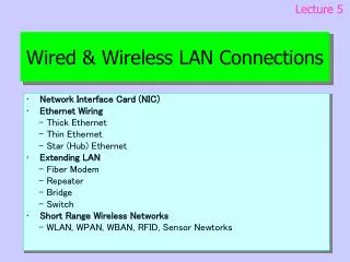
Direct connection: broadcast • Shared media Metcalfe’s Ethernet Sketch (1973) Ethernet “dominant” LAN technology: • cheap $30 for 100Mbs! • first widely used LAN technology • simpler, cheaper than token LANs and ATM • kept up with speed race: 10, 100, 1000, 10000 Mbps • wireless options
10Mb/s Ethernet Physical Layer • Each bit has a transition • Allows clocks in sending and receiving nodes to synchronize to each other • no need for a centralized, global clock among nodes!
Ethernet Format: Framing • Preamble: (synchronization) • 8 bytes, allows sender/receiver clocks to synchronize • Destination/SourceAddress: (hey Paul, Tom here) • 6 bytes each • Type: • 2 bytes, indicates higher layer protocol • 0x0800 is IP, 0x0806 is ARP • Data: 46-1500 bytes • FCS (CRC): • catches most transmission errors - errored frames dropped
Ethernet Packet Structure • 14 byte header • 2 addresses
Ethernet Addressing • 6 byte address (unique to each adapter) • Example: 08-0b-db-e4-b1-02 • 2^48 = 281 trillion; can produce 100 million LAN devices every day for 2000 years! • Interpretation of address: • Upper 24 bits OUI (Organizationally Unique Identifier) • Lower 24 bits Organization-assigned portion • Unicast: lowest bit of first byte is 0 • Multicast: lowest bit of first byte is 1 • Broadcast: ff-ff-ff-ff-ff-ff • Adaptor accept frame if and only if: • Destination address matches adapter address, or • Destination address is broadcast, or • Destination address is multicast and adapter has been configured to accept it
CSMA/CD (the polite conversationalist) carrier sense: don’t transmit if you sense someone else transmitting collision detection: abort your transmission if you sense someone else transmitting random access: wait random time before attempting a retransmission Ethernet Media sharing
nodes hub Ethernet Technologies • 10Base2: • 10Mbps, 200 meters max cable length • thin coaxial cable in a bus topology • repeaters connect multiple segments • 10BaseT / 100BaseT “fast ethernet”: • 10/100Mbps, Twisted pair • Nodes connect to a hub in “star topology” • Gigabit Ethernet: • 1Gbps, fibre or copper • Extending from LAN to MAN • 10 Gbps Ethernet available • High data speed + larger distance + increasing number of devices per LAN => switching
Twisted Pair Wire Map • EIA/TIA 568B (UGA Standard)
Standard vs Crossover Cables Card-to-Hub Wiring (Standard Cable) RD+ TD+ TD- RD- RD+ TD+ TD- RD- Card-to-Card (Hub-to-Hub) Wiring (Crossover Cable) TD+ (RD+) TD+ (RD+) TD- (RD-) TD- (RD-) RD+ (TD+) RD+ (TD+) RD- (TD-) RD- (TD-)
Power over Ethernet (PoE) http://www.nwfusion.com/news/2003/1124infrapoe.html
Most popular LAN technology nowadays 10Mb/s - 1Gb/s Each host has unique 48bit MAC address (factory assigned) Frames sent to MAC addresses To find destination MAC address, ARP protocol is used IP: 10.0.0.10 MAC: 00:00:aa:aa:aa:aa IP: 10.0.0.11 MAC: 00:00:bb:bb:bb:bb A B IP: 10.0.0.12 MAC: 00:00:cc:cc:cc:cc IP: 10.0.0.13 MAC: 00:00:dd:dd:dd:dd C D Ethernet frame Dest MAC Source MAC IP packet DestIP SourceIP Data Ethernet
ARP Query Host A Host B Broadcast Host B MAC ? Host B IP ARP Response Unicast Host B MAC Host B IP ARP: finding the MAC Address RFC 826: Address Resolution Protocol, 1982
R R S S R R R R Multicast: one to many communication • IP multicast • Application level one to many communication • multiple unicasts
1110 00000001 00000000 01011110 0 IP & Ethernet Multicast Address Mapping • IP multicast addresses (class D) range from 224.0.0.1 to 239.255.255.255 and map to Ethernet destination MAC addresses as shown below 32-bit Class D IP Address Low-order 23 bits of multicast Not mapped Group ID copied to Enet address 48-bit Ethernet Address
high byte Multicast(1) Local(1)/global(0) administration 48 bit address Multicast Addresses • Multicast revises addresses to be protocol specific: high byte, least bit is “1” if multicast. • Applications that use multicast • One-to-many IP video broadcasting • Computing clusters in Grids
Ethernet Multicast Addresses 01-00-5E-00-00-00
Switching (same as Bridging) • Goals • traffic isolation • “transparent” operation • plug-and-play • Operation • store and forward Ethernet frames • examine frame header and selectively forward frame based on MAC dest address • when frame is to be forwarded on segment, uses CSMA/CD to access segment
E0: 0260.8c01.1111 E0: 0260.8c01.2222 E1: 0260.8c01.3333 E1: 0260.8c01.4444 0260.8c01.1111 0260.8c01.3333 E0 E1 0260.8c01.2222 0260.8c01.4444 Switching Tables
X Y Segment 1 Broadcast Segment 2 Spanning Tree Protocol
Spanning tree protocol (IEEE 802.1d) • Every bridge has bridge-id • bridge-id = 2-byte priority + 6-byte MAC addr • MAC address is 00:A0:C5:12:34:56 • bridge ID is 8000:00A0:C512:3456 • Every port of bridge has • port-id = 1-byte priority + 1-byte port-number • port-cost = inversely proportional to link speed • Bridge with lowest bridge-id is root bridge • On each LAN segment, bridge with lowest path cost to root is designated bridge (use bridge-id and port-id to break ties) • A bridge forwards frames through a port only if it is a designated bridge for that LAN segment
STP terminology • Port roles: • Root port (switch port leading to root) • Designated port (LAN port leading to root) • Alternate / backup port (anything else) • Port states: • Blocking (no send/rcv, except STP bpdus) • Listening (prepare for learning/forwarding) • Learning (learn MAC addr but no forwarding) • Forwarding (send/rcv frames) • Can disable STP on port or switch • All frames are forwarded • BPDUs?
STP operation • BPDU carries 4-tuple: • <root-id, root-cost, bridge-id, port-id> • Store rcvd and send 4-tuple for each port: • port with best rcvd 4-tuple is root port • root bridge has no such port • if send 4-tuple better than rcv 4-tuple, port is designated port • rest of the ports are alternate/backup ports • Various timers
Spanning tree example DP DP DP RP DP RP RP DP DP DP DP DP root RP DP DP
New Spanning Tree Protocol versions • Implementation of : • Rapid Spanning Tree Protocol 802.1w (RSTP); • Per VLAN Spanning Tree 802.1q (PVST +); • Multiple Spanning Tree 802.1s (MST); • Load balancing across links; • Uni-Directional Link Detection (UDLD)
802.1w Rapid Spanning Tree Protocol • The IEEE 802.1w specification, Rapid Spanning Tree Protocol, provides for subsecond reconvergence of STP after failure of one of the uplinks in a bridged environment. • 802.1w provides the structure on which the 802.1s features such as multiple spanning tree operates. • There are only three port states left in RSTP corresponding to the three possible operational states Learning ,Forwarding and Discarding. • Rapid Transition to Forwarding State is the most important feature introduced by 802.1w: • RSTP actively confirms safe port transition to forwarding without relying on timers; • There is now a real feedback mechanism that takes place between RSTP-compliant bridges. • In order to achieve fast convergence on a port, the protocol relies upon two new variables: edge ports and link type.
Virtual LANs • LAN (broadcast domain) grows large • “departments” or “workgroups” not happy with big broadcast domain • Security (eavesdropping) • Bandwidth consumed by flooding/multicasting • Split LAN into multiple broadcast domains • Multiple physical LANs? • Too expensive! • People move all the time! • VLAN: logical partition of LAN
VLANs: IEEE 802.1q destination addr source addr data FCS type • “Tagged” Ethernet frames contain VLAN-id • Switch adds/removes tag when forwarding frames between trunk and non-trunk ports • Complications: • Hosts and legacy switches do not understand VLAN tags • Tag insertion/removal requires FCS recomputation • Frame length increases beyond legacy MTU 3-bit priority 1-bit CFI 12-bit VLAN id VLAN protocol id = 0x8100
VLAN Standard: IEEE 802.1q CFI-Canonical Format Identifier (Ethernet/TokenRing)