Download
1 / 31
310 likes | 324 Vues
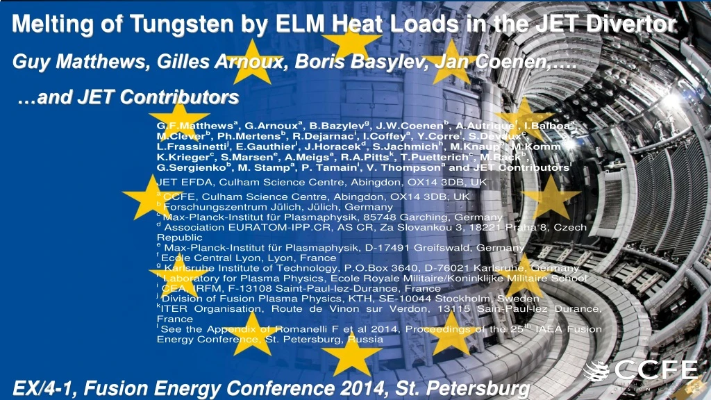
Melting of Tungsten by ELM Heat Loads in the JET Divertor Guy Matthews, Gilles Arnoux, Boris Basylev, Jan Coenen,…. …and JET Contributors. EX/4-1, Fusion Energy Conference 2014, St. Petersburg. Outline. Background The JET melt experiment Simulation of the results

E N D
Melting of Tungsten by ELM Heat Loads in the JET Divertor Guy Matthews, Gilles Arnoux, Boris Basylev, Jan Coenen,…. …and JET Contributors EX/4-1, Fusion Energy Conference 2014, St. Petersburg
Outline • Background • The JET melt experiment • Simulation of the results • Conclusions and future plans
Decision on material for ITER first divertor Risks for tungsten melting in early ITER operation had to be reviewed by IO
Bulk W melting well studied in medium sized tokamaks Bulk melting can cause disruptions = dangerous for ITER Bulk melting risk was considered low for ITER divertor due to tile shaping & protection systems ASDEX-Upgrade divertor manipulator
Looking down into the tungsten divertor - after The JET tungsten divertor Tungsten lamella shaping and divertor protection systems work in JET at ITER relevant inter-ELM heat fluxes 2011As installed 2012After ~3500 pulses~20Hrs plasma Stack A Stack B
W melting by ELMs QSPA ELM simulations looked worrying for ITER …but plasma pressure lower and B higher in ITER (and JET) stabilises surface waves N. Klimov et al., JNM 390-391 (2009) 721 QSPA-T W target Extrapolation to ITER requires abenchmark for the MEMOS code JET is capable of achieving a similar transient heat-flux at normal incidence Plasma flow direction 6 q > 2.2 MJm-2, t ~0.5 ms 3.8 MJm-2 for a 1.5 ms pulse (ITER minimum tTQ)
Typical temperature rise due to ELMs in JET Geometric factor for a vertical edge ~ ×20 Surface T depends mainly on pedestal pressure not ELM size! So increase heating power or Ip to raise T Existing data – normal lamellasT during ELMs Temperature rise (C) [T.Eich] ITER ~105 Pa Pedestal pressure (Pa) 7
Outline • Background • The JET melt experiment • Simulation of the results • Conclusions and future plans
Exposing a tungsten edge in JET A JET pulse 84779 B q|| A B
Typical JET W melt pulse 3MA/2.9T 23MW ~3GWm-2 ~0.5GWm-2 300kJ ELMs q||
Melt pulses are reproducible and no disruptions Special lamella Temperature from IR (C) Standard (Ref.) lamella Time (s)
Special lamella 5.5mm LFS HFS 84686 – Before melting q|| q|| Special lamella 5.5mm Special lamella 5.5mm Special lamella 5.5mm LFS LFS HFS
Special lamella LFS HFS After 84724
Special lamella LFS HFS After 84778
Special lamella LFS HFS After 84779
Special lamella LFS HFS After 84781
Special lamella LFS HFS After 84782
JxB B Jthermionic After 84783 5.5mm LFS HFS Erosion: 150-300m per pulse, 5-10m per ELM (frequency 30Hz) Total volume moved: ~6mm3
Erosion centres on the ELM footprint Tref(C) 20
Laser blow off with W target W droplet event during melt pulse Indirect evidence for W droplet expulsion A few droplets reach the main plasma with diameters ~ 100m- Small perturbations only and no disruptions 21
Outline • Background • The JET melt experiment • Simulation of the resultsMEMOS = key tool used for ITER predictionsStefan problem in 3D geometry accounting surface evaporation, melting and re-solidification solved by implicit method- Surface power density vs time from IR is the input- Vapour shielding - Temperature dependent thermophysical data applied- Moving boundaries are attached to melt layers- All forces: Gradient of plasma pressure, gradient of surface tension, JxB, tangential friction force[Bazylev TH/P3-40] • Conclusions and future plans 22
Power density q|| from reference lamellas IR camera T(t) Theodor 2D inverse code qn (MWm-2) q|| = qn / sin MEMOS 3D B Reference lamellas
Power density on the special lamella PIC model says: fs >0.6 during ELMs fs~1 inter-ELM and L-mode MEMOS input = qn from IR (Theodor) fs iterated to match: evaporation rate, synthetic IR image and Planck radiation q|| from reference lamellas qn= q|| sin qs Special lamella qs = fs q|| cos 24 qs = fs q|| cos
fs chosen to fit evaporation rate and Planck radiation Temperature #84779 – IR (unresolved) and peak (MEMOS) Melting IR MEMOS fs=1 Best fit to all data with fs=0.4 W evaporation rate from WI (400.88nm) MEMOS fs=0.4 25
W melt evolution #84779 – MEMOS [Bazylev TH/P3-40] fs=0.4 26
Hierarchy of forces – MEMOS [Bazylev TH/P3-40] JET pulse #84779 - MEMOS B m m Surface: -200 to +400m Surface: -40 to +10m Melt depth and motion match JET data Shadow JxB HFS J 60mm 2.5mm LFS Plasma pressure (6kPa) +surface tension gradients + thermionic emission (JxB) Plasma pressure (6kPa) +surface tension gradients
Future JET plans • New lamella at 15: • Fully resolved IR temperature • Grazing field angle / more ITER-like • Simpler geometry Conclusions W melting by ELMs in JET provided important inputs to ITER: • Shallow melts with a few small droplets ejected but no disruptions • JET melt results are consistent with MEMOS assuming J×B dominant • Unexpectedly large power mitigation factor found for exposed W edge 28
Thermionic emission during ELM - MEMOS JET pulse #84779 - MEMOS [Bazylev TH/P3-40] Unlike JET experiment, suppression of thermo electron emission is predicted in ITER due to grazing field angles
Larmor radius smoothing - PIC code [Dejarnac NF] Equivalent to fs~0.8 - Calculated for ELMs only - insufficient to explain fs=0.4 in H-mode - No effect expected in L-mode where we find fs=0.2 30
MEMOS suggests significant vapour shielding …..but we are not able to prove it experimentally due to lack of a consistent physics model for fs=0.4 in H-mode and fs=0.2 in L-mode #84779