Download
1 / 58
1.21k likes | 2.58k Vues
CHAPTER. Body Control Modules. 13. Instructor Name: (Your Name ). Learning Objectives. Explain the concept of virtual fusing List the type of inputs and outputs used by a typical body control module

E N D
CHAPTER Body Control Modules 13 Instructor Name:(Your Name)
Learning Objectives • Explain the concept of virtual fusing • List the type of inputs and outputs used by a typical body control module • Discuss the reasons that most electronic control modules used in modern trucks make use of a reference ground • Discuss the difference between a conventional switch and diagnosable switch • Describe how a body control module can act as a turn signal flasher
Learning Objectives (continued) • Retrieve DTC’s stored in memory related to the body controller • List the main components of the International Diamond Logic® and Freightliner® Smart Plex™ multiplexed electrical systems • Describe how a Freightliner Smart Switch operates • Explain the concept of ghost voltage and describe how it can lead to confusion when diagnosing an electrical problem
International Multiplexed Electrical System • Referred to as the Diamond Logic electrical system • Between 2001-2006 body control modules were referred to as electrical system controller (ESC) • In 2007 the name was changed to the body controller
International ESC Figure 13-1 International electrical system controller (ESC).
International Body Controller Figure 13-2 International body controller.
Overview of Body Controller Figure 13-3 Overview of body controller.
Tech Tip Think of the J1939 data link as both being an input and an output device for most electronic devices. The messages received by a module are inputs; the messages sent by a module are the outputs.
Typical Body Control Module Horn Circuit Figure 13-5 Typical body control module horn circuit.
Body Controller Outputs • The body controller has three main types of outputs: • High side drivers • Low side drivers • Messages transmitted on the J1939 data link
High Side Driver • Capable of sourcing high levels of current • The high side drivers used in body controllers are power MOSFETs (FETs) • Some FETs are capable of sourcing 20A continuously • Smart FETs can monitor the amount of current that the FET is conduction
Current Feedback For Virtual Fusing Figure 13-6 The high side driver measures the current being conducted and feeds back this information to the microprocessor as a proportional voltage.
Low Side Drivers • Current ratings of 1A or less • Commonly used in body controllers • Low side drivers sink a path to ground • Typically used to energize relay coils or small solenoids
Body Controller Inputs • There are three main types of inputs to the body controller: • Hardwired inputs from switches and sensors • Messages received from a proprietary switch data link • Messages received from the J1939 data link
Hardwired Inputs • Conventional switch to control electrical devices • Reference ground is a single ground that all sensors and switches share • Reference ground is connected to chassis ground but in one location usually inside the electronic module
Common Reference Ground Located in Body Controller Figure 13-7 The common reference ground point inside of body controller is connected to chassis ground at only one location.
CAUTION It is vital that any electronic system that uses a reference ground only be grounded in accordance with OEM recommendations. Even though reference ground may appear to be the same as chassis ground, connecting the reference ground to chassis ground outside the electronic module may result in the truck having intermittent EMI induced problems that are nearly impossible to duplicate or troubleshoot.
Open and Closed Switches with Digital Input Figure 13-8 Open switch (upper) and closed switch (lower) with digital input.
Open Circuit Prevents Digital Input From Detecting Switch is Closed Figure 13-9 Open circuit prevents digital input from detecting that switch is closed; input voltage should be 0V with switch closed, but is actually +12V.
Diagnosable Switch With Contacts Open and Closed Figure 13-10 Diagnosable switch with contacts open and closed.
Diagnosable Switch Open;8V at the Input Terminal Figure 13-11 Diagnosable switch open; 8V at input terminal.
Diagnosable Switch Closed; 6V at the Input Terminal Figure 13-12 Diagnosable switch closed; 6V at input terminal.
Diagnosable Switch Open Circuit; 12V at the Input Terminal Figure 13-13 Diagnosable switch open circuit; 12V at input terminal.
Switch Packs • International trucks with body controllers use switch packs using J1708/J1578 specification data link • This proprietary link is not the same as the J1708/J1587 data link connected to the power train or ECM modules • Switch packs are rockers that require switch actuators installed in them
Switch Pack with Switch Actuators Removed Figure 13-14 Switch pack with the switch actuators removed.
Tech Tip Think of high side drivers as being like conventional relays. A small signal provided by the microprocessor is used to control a large amount of current.
Body Controller Headlight Circuit Figure 13-15 Body controller headlamp circuit. EGC contains headlamp switch.
Turn-Signal System, International Truck With Body Controller Figure 13-16 Turn-signal system on International trucks with body controller. Two switches are inputs; four high side drivers are outputs.
Tech Tip The body controller only powers the applicable trailer light relay control circuit. The body controller does not directly supply the current to the trailer lighting. A conventional CPD such as a fuse or a circuit breaker in the PDC is used to protect the trailer wiring, not virtual fusing.
A/C System Inputs; Outputs Is A/C Clutch High Side Driver Figure 13-17 Air conditioning system inputs; output is A/C clutch high side driver.
Cruise Control Related Inputs Output is J1939 Message to Engine ECM Figure 13-18 Cruise control related inputs; output is J1939 message to engine ECM.
Primary and Secondary Air Pressure Measurement System Figure 13-19 Primary and secondary air pressure measurement system.
Windshield Wiper System Outputs Figure 13-20 Windshield wiper system outputs; one high side driver and two low side drivers.
Wiper Switch Inputs and Truth Table Figure 13-21 Wiper switch inputs and truth table.
Tech Tip An open windshield wiper switch connection on an International truck with a body controller causes the wiper to operate at high speeds at any time the key switch is in the ignition position. Additionally, a short to ground of the windshield washer pump control circuit will cause the windshield wipers to operate at low speed any time the key switch is in the ignition position because the controller is falsely detecting that the washer switch is depressed.
Freightliner Multiplexed Electrical System • Freightliner refers to their multiplexed electrical system as SmartPlex™ • The bulkhead module (BHM) acts as the primary command module for body and chassis electrical systems. • The chassis module (CHM) is the other standard electronic module • The CHM is a slave or dependent that receives commands from the BHM
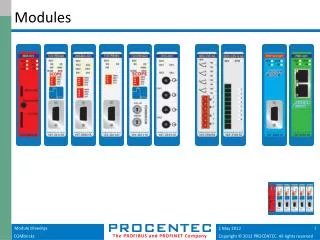
Freightliner SmartPlexTM Electronic Module Locations Figure 13-22 Freightliner SmartPlexTM electronic module locations.
Bulkhead Module (BHM) • Main electronic controller for Freightliner SmartPlexTM electrical system • The BHM is connected to the J1939 data link and transmits and receives information from other electronic modules • The BHM is hardwired to several inputs in the cab • Direct hardwired high side outputs include horn, dome light, left side low-beam and high beam headlights
Freightliner Smart Switch Schematic Figure 13-25 Freightliner smart switch schematic.
Chassis Module (CHM) • Contains several high side driver FETs that source current to several chassis electrical features • The CHM is dependent on commands from the BHM via the J1939 data link • High side driver outputs include park and marker lights, back-up lamps, turn signal lamps, right side high and low beam headlights and fog lamps
Freightliner Multifunction Switch Figure 13-28 Freightliner multifunction switch.
Freightliner Multiplexed Headlamp Control Figure 13-29 Freightliner multiplexed headlamp control.
Troubleshooting The Multiplexed Truck • Best if performed with OEM diagnostic software and a PC, referred to as a electronic service tool (EST) • Software for Freightliner trucks is ServiceLink® • Software for International trucks is diamond Logic® • This software permits viewing diagnostic trouble codes by the body controller and EGC, along with fault descriptions
International Diagnostic Code Retrieval • Place the ignition switch in the ignition or accessory position • Set the park brake • Depress the cruise control ON and RESUME switches at the same time • The EGC will indicate the number of DTCs that exist
Diagnostic Trouble Codes Display Figure 13-32 Diagnostic trouble codes as displayed in instrument panel cluster odometer display.
SAE J1939 Suspect Parameter Number Figure 13-33 SAE J1939 suspect parameter number (SPN).
SAE J1939 Failure Mode Indicator Figure 13-34 SAE J1939 failure mode indicator.
ORH Condition at a Pulled-Up Input With Open Circuit Figure 13-36 ORH condition at a pulled-up input with an open circuit.
ORL Condition at a Pulled-Up Input with Grounded Circuit Figure 13-37 ORL condition at a pulled-up input with a ground circuit.
ORL Condition at a Pulled-Down Input With Open Circuit Figure 13-38 ORL condition at a pulled-down input with an open circuit.