Download
1 / 1
10 likes | 134 Vues
Analog. Circuits. and. (. ). Electrodes. pq. D. L. sin22. l. A. DAC. 0. 0. D. q. 18. 16. Sig Gen. (. ). pq. D. L. cos22. l. B. 0. 18. f. dds. A. DAC. 7. 7. 16. B. 7. p. cos(2). kn. n. V. å. r. ,0. y. =. k. 1. k. ,0. ADC. p. sin(2). kn. 0. n.

E N D
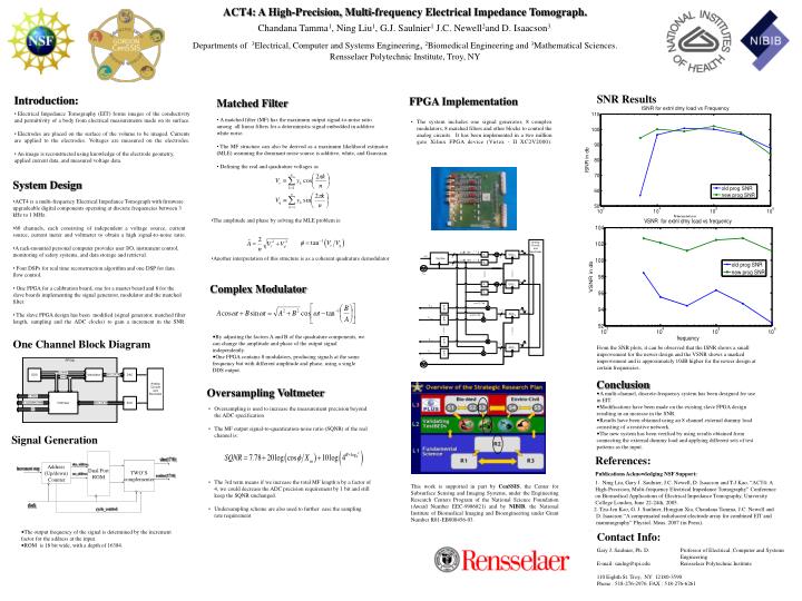
Analog Circuits and ( ) Electrodes pq D L sin22 l A DAC 0 0 D q 18 16 Sig Gen ( ) pq D L cos22 l B 0 18 f dds A DAC 7 7 16 B 7 p cos(2) kn n V å r ,0 y = k 1 k ,0 ADC p sin(2) kn 0 n 16 V å q ,0 = k 1 n V å r ,7 y = k 1 k ,7 ADC 7 n 16 V å q ,7 = k 1 f smp ACT4: A High-Precision, Multi-frequency Electrical Impedance Tomograph. Chandana Tamma1, Ning Liu1, G.J. Saulnier1 J.C. Newell2and D. Isaacson3. Departments of 3Electrical, Computer and Systems Engineering,2Biomedical Engineering and 3Mathematical Sciences. Rensselaer Polytechnic Institute, Troy, NY SNR Results • Introduction: • Electrical Impedance Tomography (EIT) forms images of the conductivity and permittivity of a body from electrical measurements made on its surface. • Electrodes are placed on the surface of the volume to be imaged. Currents are applied to the electrodes. Voltages are measured on the electrodes. • An image is reconstructed using knowledge of the electrode geometry, applied current data, and measured voltage data. FPGA Implementation • Matched Filter • A matched filter (MF) has the maximum output signal-to-noise ratio among all linear filters for a deterministic signal embedded in additive white noise. • The MF structure can also be derived as a maximum likelihood estimator (MLE) assuming the dominant noise source is additive, white, and Gaussian. • Defining the real and quadrature voltages as • The system includes one signal generator, 8 complex modulators, 8 matched filters and other blocks to control the analog circuits. It has been implemented in a two million gate Xilinx FPGA device (Virtex - II XC2V2000). • System Design • ACT4 is a multi-frequency Electrical Impedance Tomograph with firmware upgradeable digital components operating at discrete frequencies between 3 kHz to 1 MHz. • 60 channels, each consisting of independent a voltage source, current source, current meter and voltmeter to obtain a high signal-to-noise ratio. • A rack-mounted personal computer provides user I/O, instrument control, monitoring of safety systems, and data storage and retrieval. • Four DSPs for real time reconstruction algorithm and one DSP for data flow control. • One FPGA for a calibration board, one for a master board and 8 for the slave boards implementing the signal generator, modulator and the matched filter. • The slave FPGA design has been modified (signal generator, matched filter length, sampling and the ADC clocks) to gain a increment in the SNR. • The amplitude and phase by solving the MLE problem is: • Another interpretation of this structure is as a coherent quadrature demodulator Complex Modulator • By adjusting the factors A and B of the quadrature components, we can change the amplitude and phase of the output signal independently. • One FPGA contains 8 modulators, producing signals at the same frequency but with different amplitude and phase, using a single DDS output. One Channel Block Diagram From the SNR plots, it can be observed that the ISNR shows a small improvement for the newer design and the VSNR shows a marked improvement and is approximately 10dB higher for the newer design at certain frequencies. Conclusion Oversampling Voltmeter • A multi-channel, discrete-frequency system has been designed for use in EIT. • Modifications have been made on the existing slave FPGA design resulting in an increase in the SNR. • Results have been obtained using an 8 channel external dummy load consisting of a resistive network. • The new system has been verified by using results obtained from connecting the external dummy load and applying different sets of test patterns as the input. • Oversampling is used to increase the measurement precision beyond the ADC specification • The MF output signal-to-quantization-noise ratio (SQNR) of the real channel is: • The 3rd term means if we increase the total MF length n by a factor of 4, we could decrease the ADC precision requirement by 1 bit and still keep the SQNR unchanged. • Undersampling scheme are also used to further ease the sampling rate requirement Signal Generation Dual Port ROM References: Publications Acknowledging NSF Support: 1. Ning Liu, Gary J. Saulnier, J.C. Newell, D. Isaacson and T-J Kao. “ACT4: A High-Precision, Multi-frequency Electrical Impedance Tomography” Conference on Biomedical Applications of Electrical Impedance Tomography, University College London, June 22-24th, 2005. 2. Tzu-Jen Kao, G. J. Saulnier, Hongjun Xia, Chandana Tamma, J.C. Newell and D. Isaacson “A compensated radiolucent electrode array for combined EIT and mammography” Physiol. Meas. 2007 (in Press). . sine(17:0) TWO’S complementer Address (Up/down) Counter sine_address increment step cos_address cosine(17:0) This work is supported in part by CenSSIS, the Center for Subsurface Sensing and Imaging Systems, under the Engineering Research Centers Program of the National Science Foundation (Award Number EEC-9986821) and by NIBIB, the National Institute of Biomedical Imaging and Bioengineering under Grant Number R01-EB000456-03. clock cycle_control • The output frequency of the signal is determined by the increment factor for the address at the input. • ROM is 18 bit wide, with a depth of 16384. Contact Info: Gary J. Saulnier, Ph. D. Professor of Electrical, Computer and Systems Engineering E-mail: saulng@rpi.edu Rensselaer Polytechnic Institute 110 Eighth St. Troy, NY 12180-3590 Phone : 518-276-2976 FAX : 518-276-6261