Download

1 / 26
260 likes | 271 Vues
Mars Atmosphere and Volatile EvolutioN (MAVEN) Mission. Particles and Fields Package Critical Design Review May 23 -25, 2011 Integration and Test Dave Curtis PFP Package Manager. PFP Block Diagram. 10cm. Integration and Test Plan. MAVEN_PF_SYS_0022 I&T Plan submitted to Project

E N D
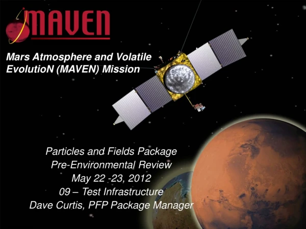
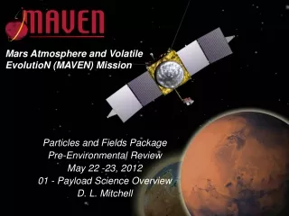
Mars Atmosphere and Volatile EvolutioN (MAVEN) Mission Particles and Fields Package Critical Design Review May 23 -25, 2011 Integration and Test Dave Curtis PFP Package Manager
PFP Block Diagram 10cm
Integration and Test Plan MAVEN_PF_SYS_0022 I&T Plan submitted to Project Matches up with PFP Verification & Validation Plan Philosophy: Requirements are verified as early as possible at a low level Verifies subsystems, Retires risk Requirements are verified at the highest level of assembly possible Identify requirements which cannot be verified at a system level and ensure they are verified at the lower level before integrating Maintain flexibility in test sequencing to maintain schedule Full set of Protoflight level tests on FM Typical Test Levels: Subassembly (circuit board, mechanism): functional Component: functional, mass properties, vibration, TV, magnetics, deployments Instrument: functional, calibration, interface Package: functional, EMC, Package Self-compatibility, interface
MAG I&T MAG is fabricated at GSFC MAG will be functionally tested, calibrated, and the sensor vibrated at GSFC Using SSL-provided PFDPU simulator EGSE MAG will be delivered to SSL and the electronics will be integrated into the PFDPU Followed by functional testing to verify performance not degraded MAG electronics environmental test with PFDPU Following Suite I&T and EMC tests, MAG sensor Thermal Vac will take place at SSL With PFDPU outside the chamber
SEP I&T Instrument fabricated at SSL Board level functional testing Attenuator functional testing SSD test, Select Magnets test, select Instrument integration Instrument bench CPT Uses radiation source Uses PFDPU Simulator EGSE Collimator scattered light test Instrument Calibrated Existing automated calibration facility End-to-End test SEP electronics integrated into the PFDPU Followed by functional testing to verify performance not degraded SEP Electronics (DAP) environmental tests with PFDPU Following Suite I&T and EMC tests, SEP Sensor: Vibration (near by subcontractor facility) Magnetics Screening Thermal Vac
LPW / EUV I&T LPW Booms and Preamps fabricated at SSL Preamps will be thermal vac tested separately before integration due to the extended temperature range EUV sensor and LPW electronics fabricated at LASP Board level functional using SSL-provided PFDPU simulator EGSE EUV calibration testing LPW electronics integrated into the PFDPU Followed by functional testing to verify performance not degraded LPW Electronics (BEB/DFB) environmental test with PFDPU Following Suite I&T and EMC tests: LPW Boom & EUV Vibration (near by subcontractor facility) LPW boom & EUV Magnetics Screening LPW Boom & EUV Thermal Vac EUV environments at LASP, LPW Boom at SSL
LPW Boom Deployments Boom deployment testing takes place at the component level (LPW). A minimum of 2 full deployments will take place on each unit prior to the start of the environmental test program. In addition, during component level thermal vacuum tests, there will be one deployment at hot and one at cold. LPW Boom cannot be deployed at the Spacecraft level Difficulty G-negating deployment safely During functional tests at the spacecraft level, actuator simulators will be used to verify the ability of the system to run the deployment.
STATIC, SWIA I&T Instrument fabricated at SSL Board level functional testing MCP test Instrument integration Instrument bench CPT No high voltage Uses internal test pulser Uses PFDPU Simulator EGSE Instrument calibrated at SSL New SWIA/STATIC automated calibration facility End-to-End test Following Suite I&T and EMC tests: Vibration (near by subcontractor facility) STATIC Acoustics (subcontractor) Magnetics Screening Thermal Vac
SWEA I&T SWEA Analyzer if fabricated in CESR (France) Board level functional testing MCP test Instrument integration Instrument calibrated at CESR Existing calibration facility End-to-End test Analyzer delivered to SSL Digital Electronics & LVPS fabricated at SSL Board level functional tests Instrument is integrated at SSL Bench CPT using PFDPU Simulator EGSE Instrument calibrations at SSL Existing calibration facility Subset of CESR tests to ensure system functionality Following Suite I&T and EMC tests: Vibration (near by subcontractor facility) Magnetics Screening Thermal Vac
PFDPU I&T PFDPU electronics (excluding instrument electronics) fabricated at SSL Board level functional tests Uses Instrument Simulator GSE, Spacecraft Simulator GSE PFDPU integrated & tested Install Acceptance-tested Flight Software Integrate Instrument Electronics Integrated PFDPU CPT Following Suite I&T and EMC tests: Vibration (near by subcontractor facility) Magnetics Screening Thermal Vac
Package I&T The PFDPU is integrated (DCB, REG, IIB, MAG, SEP, LPW electronics) Functional test to verify interfaces and compatibility The remaining instruments are integrated SWEA, SWIA, STATIC A baseline CPT test is performed A self-compatibility test is performed Verify instruments don’t interfere with each other Pre Environmental Review EMC testing is completed at the Package level RE, RS, CE, CS, Transients, Inrush Flight or flight like harnesses Near-by subcontractor facility Instruments bagged and purged Remaining environments are done at the Component level Final pre-delivery package CPT STATIC may be tested and delivered separately as it is needed first at LM
EMC Tests Levels per ERD: Radiated Emissions RE102 Radiated Susceptibility RS103 Conducted Emissions CE101/102 Conducted Susceptibility CS101, CS115 Inrush, Bonding, Isolation tests
Magnetics Test Measure the powered off dipole Target is 25mA-m2 Measure power on/off and transient and AC fields Use SSL Magnetics screening facility
Dynamics Structural Loads by Analysis Pressure Profile by rule-of-thumb Self-shock Cover open, deploy Spacecraft shock deferred to ATLO Acoustics Deferred to ATLO Except STATIC Protoflight Random Vibration ERD levels Local contractor
Thermal Vac SSL Facilities 5 chambers available with various configurations Thermal Balance depending on results of thermal analysis Current plan calls for SWEA, STATIC Thermal Balance, TBR 8 cycles per ERD and GEVS to predicts/AFT +/-10C CPT hot and cold first cycle; LPT thereafter Nominally separate due to different environments But may consider combining some tests if ranges compatible Last cycle followed by bakeout with TQCM to verify outgassing
SSL Integration and Test Facilities Cleanroom (with 5 THEMIS probes) ‘Snout’ TVac Chamber (LPW deploy) Magnetics Screening Station Calibration Chamber
Contamination Control PFP instruments shall be assembled in clean room facilities Sensitive detectors (SWEA, SWIA, STATIC, SEP, EUV) shall be assembled on flow benches Components will be bagged when not in clean room facilities LN2 boil-off shall be used to purge the instruments SWEA, SWIA, STATIC, SEP, EUV Limited times off purge Instruments shall be maintained at VC-HS levels cleaned with IPA by PFP personnel Planetary Protection Implementation verified by Assays
Performance Tests Comprehensive Performance Test (CPT) covers all functions and modes of operation to the extent possible Limited Performance Test (LPT) is a subset of CPT covering representative modes and functions in a limited time No external stimulus Provides repeatable functional tests for use throughout I&T and ATLO Some adaptation required at different levels of assembly; instrument, package, spacecraft Provides data for performance trending
Integration and Test Procedures Each test shall be documented by a Test Procedure Test procedure shall identify L3 requirements to be verified by the test Test procedure shall include pass/fail criteria System Engineer, QA, Subsystem lead to sign off on proc before use System Engineer, QA to sign off on completed as-run proc QA to ensure Red-lines to be transferred into proc before next use Each completed test to be documented by a Test Report EM and subassembly test reports may be a combination of the as-run proc and lab notebook System Engineer to sign off on test reports, and determine if test adequately verifies associated requirements Discrepancies found during tests to be documented in a Problem Failure Report (PFR) Starting with first functional tests at flight subassembly level Includes any problem (including software) not immediately identified as a test setup or operator problem which cannot stress the flight article QA will track PFRs to closure with concurrence of the Failure Review Board Waivers by Project CCR process System Engineer to track Completed Verifications on a Verification Matrix
ATLO Assembly, Test, and Launch Operations Takes place at Lockheed Martin in Denver and Kennedy Space Center in Florida SWEA, SWIA, STATIC will be removed after spacecraft environments and returned to SSL for a functional test in vacuum to verify no damage occurred during spacecraft environments
ATLO Issues Contamination Control Dust Covers Purge Magnetics Keep high fields away from sensors (tools, equipment) Stimulus for CPT LPW function generator EGSE SEP radiation source EUV lamp LPW Boom Deployment Cannot deploy booms at system level due to G-negation issues Use simulators to verify ability to fire actuators High Voltage SWEA, SWIA, STATIC HV cannot be operated in air Limits ability to do end-to-end tests Green-tag enable plugs protect against accidental operation Can operate in thermal vac, but not a complete test Need a post-environments test at SSL to fully verify functionality These issues are covered in the PFP to Spacecraft ICD.
I&T Schedule Milestones LPW DFB, BEB from LASP 12/2011 EUV from LASP 2/2012 SWEA Analyzer from CESR 12/2011 MAG from GSFC 4/2012 SEP, LPW, PFDPU to PFP I&T 4/2012 SWEA, SWIA, STATIC to PFP I&T 5/2012 PFP PER 5/2012 PFP EMC 6/2012 Component Qualification Start 6/2012 PFP PSR 8/2012 PFP due at LM 11/13/2012