Download
1 / 25
250 likes | 453 Vues
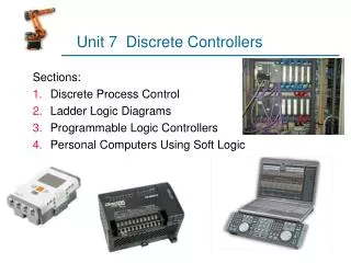
Unit 4 Design and Synthesis of Datapath Controllers. Digital systems Control-dominated systems : being reactive systems responding to external events, such as traffic controllers, elevator controllers, etc

E N D
Unit 4 Design and Synthesis of Datapath Controllers Department of Communication Engineering, NCTU
Digital systems • Control-dominated systems :being reactive systems responding to external events, such as traffic controllers, elevator controllers, etc • Data-dominated systems :requiring high throughput data computation and transport such as telecommunications and signal processing • Sequential machines are commonly partitioned into data path units and control units Datapath Logic Control inputs FSM Control signals Clock DatapathRegisters Department of Communication Engineering, NCTU
Datapath units consist of: • Arithmetic units : • Arithmetic and logic units (ALU) • Storage registers • Logic for moving data : • through the system • between the computation units and internal registers • to and from the external environments • Control units are commonly modeled by • State transition graphs (STGs) • Algorithm state machine (ASM) charts for FSM • A combined control-dataflow sequential machine is modeled by ASM and datapath (ASMD) charts Department of Communication Engineering, NCTU
Algorithm State Machine (ASM) Charts • State transition graphs only indicate the transitions that result from inputs • Not only does ASM display the state transitions, it also models the evolution of states under the application of input datas • An ASM chart is formed with three fundamental elements Department of Communication Engineering, NCTU
Start En C <= C+1 • Both Mealy and Moore machines can be represented by ASM • The outputs of a Moore machine are listed inside a state box • Conditional outputs (Mealy outputs) are placed in conditional output boxes Department of Communication Engineering, NCTU
A sequential machine is partitioned into a controller and a datapath, and the controller is described by an ASM • The ASM chart can be modified to link to the datapath that is under control of the ASM • The modified ASM is referred to as the algorithm state machine and datapath (ASMD) chart • ASMD is different from ASM in that :each of the transition path of an ASM is annotated with the associated concurrent register operations of datapath Department of Communication Engineering, NCTU
An ASMD chart for a up-down counter Up-down counter with asynchronous reset Up-down counter with synchronous reset Count <= 0 Count <= 0 Reset Count <= Count - 1 Count <= Count + 1 Start Start Clr Count <= Count - 1 Up Up Count <= Count + 1 Department of Communication Engineering, NCTU
Start En C <= C+1 • ASM v.s. ASMD charts for a counter with enable ASM chart representation ASMD chart representation Start Count <= Count + 1 En Enable DP Department of Communication Engineering, NCTU
Unit 4-1 UART Design Department of Communication Engineering, NCTU
Most computers and microcontrollers have one or more serial data ports used to communicate with serial input/output devices • The serial communication interface, which receive serial data, is often called a UART (Universal Asynchronous Receiver-Transmitter) • One application of a UART is the modem (modulator-demodulator) that communicates via telephone lines Department of Communication Engineering, NCTU
Features of UARTs • There is no clock for UARTs • Data (D) is transmitted one bit at a time • When no data is being transmitted, D remains high • To mark the transmission, D goes low for one bit time, which is referred to as the start bit • When text is being transmitted, ASCII code is usually used • ASCII is 7-bit in length the 8th bit is used for parity check Department of Communication Engineering, NCTU
After 8 bits are transmitted, D must go high for at least one bit time • When receiving, the UART detects the start bit, receives the 8 data bits, and converts the data to parallel form when it detects the stop bit • The UART must synchronize the incoming bit stream with the local clock • The number of bits transmitted per second is often referred to the BAUD rate Department of Communication Engineering, NCTU
Design of a simplified UART • TDR : transmit data register, TSR : transmit shift register • RDR : receive data register, RSR : receive shift register • SCCR : serial communication control register • SCSR : serial communications status register Department of Communication Engineering, NCTU
Procedure for the data transmission of the UART :(TDRE is set when TDR is empty) • A microcontroller waits TDRE=1 load TDR TDRE=0 • The UART moves data from TDR to TSR and TDRE=1 • Output a start bit (0) shift right TSR stop bit (1) Department of Communication Engineering, NCTU
ASM for TX Department of Communication Engineering, NCTU
The operation of the UART receiver : • When detecting a start bit, the UART starts reading the remaining bits serially and shifts them into the RSR • When the stop bit is received, load RSR to RDR and RDRF=1 • If RDRF=1, the microcontroller read RDR and RDRF = 0 Department of Communication Engineering, NCTU
Key points for designing a UART receiver • The bit stream is not synchronized with the local Bclk • The bit rate of the incoming RxD differs from Bclk by a small amount could end up reading some bits at the wrong time • To avoid this problem, sample RxD eight times each bit time • When RxD first goes to 0, check for four consecutive 0’s. If this is true waits for 8 more BclkX8 star reading the 1st bit waits for 8 more BclkX8 read 2nd bit and so on Department of Communication Engineering, NCTU
BAUD generator • Suppose the system clock 8 MHz and we want BAUD rates 300, 600, 1200, 2400, 4800, 9600, 19200 and 38400 • Selection for BAUD rates (Notice!! set default rate at 38462) Department of Communication Engineering, NCTU
Input/Output (I/O) interface • TIE and RIE are set by the microcontroller (uC) • SCI_IRQ is generated for uC when RDRF or OE =1 • When TIE =1, SCI_IRQ is generated when TDRE =1 • Data BUS RDR, SCSR and hi-Z • Data BUS TDR and SCCR Department of Communication Engineering, NCTU
Input/Output (I/O) interface • Memory mapping of controller registersADDR WR Action00 0 DBUS RDR00 1 TDR DBUS 01 0 DBUS SCSR01 1 DBUS hi-Z1x 0 DBUS SCCR 1x 1 SCCR DBUS • Notice that the port to DBUS must be tri-state buffered and held hi-Z whenever not outputting data to DBUS Department of Communication Engineering, NCTU
q Addr TX FIFO16 TX Data In UART used_dw DBUS RX wr_req Full WR UART_IRQ rd_req Empty CS CLK Reset_N CLK Reset_N • Transmit FIFO controller • Generate a synchronous FIFO of 16 bytes Department of Communication Engineering, NCTU
TXFIFO16 timing Department of Communication Engineering, NCTU
Transmit FIFO controller • Generate a synchronous FIFO of 16 bytes q Addr TX FIFO16 TX Data In UART used_dw DBUS RX wr_req Full WR UART_IRQ rd_req Empty CS CLK Reset_N CLK Reset_N Department of Communication Engineering, NCTU