Download
1 / 32
790 likes | 2.25k Vues
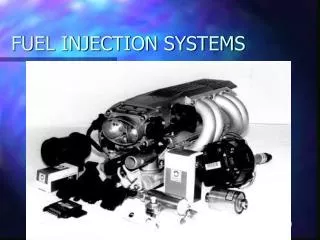
Fuel Injection System. Fuel Injection System. Uses pressure (not Vacuum) from an electrical pump to spray fuel into the intake manifold. Provides the engine with proper air-fuel ratio (14.7 : 1). Fuel Injection System. Advantages. Improved Atomization . Better fuel flow .

E N D
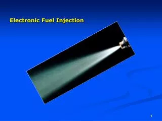
Fuel Injection System • Uses pressure (not Vacuum) from an • electrical pump to spray fuel into the • intake manifold. • Provides the engine with proper • air-fuel ratio (14.7 : 1)
Fuel Injection System Advantages • Improved Atomization • Better fuel flow • Smoother idle • Improved fuel economy • Lower emissions • Better cold weather drivability • Increased engine power • Simpler
Fuel Injection System Atmospheric Pressure • Pressure formed by the air • surrounding the earth. • Atmospheric pressure is 14.7psi • at sea level. • Any space with less than 14.7psi • at sea level has vacuum. • Engine acts as a vacuum pump, • producing vacuum in the intake • manifold.
Fuel Injection System Engine Throttle Valve • Controls air flow and gasoline to power engine. • When butterfly valve is closed it restricts air-flow and the • resulting flow of fuel into the engine. • When accelerator is pressed, the air-flow is increased in the • intake manifold. • Engine sensors detect the resulting changes and increase fuel • flow through the injectors.
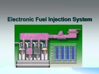
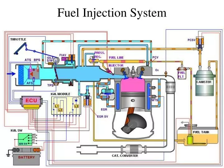
Fuel Injection System Electronic Fuel Injection uses various engine sensors and control module to regulate the opening and closing of injector valve. • Fuel delivery system • Air induction system • Sensor system • Computer control system
Fuel Delivery system • Electrical Fuel Pump draws fuel from • tank and forces it into the regulator. • Pressure Regulator controls the amount • of pressure that enters the injector and any • extra fuel is returned to the fuel tank. • Fuel Injector is simply a coil or solenoid • operated valve. • Spring pressure holds the injector closed. • When engaged, the injector sprays fuel • into the engine. Injector Pulse Width indicates the time each Injector is energized (Kept Open).
Air Induction System • Air filter • Throttle valve • Sensors • Connecting ducts
Sensor System • Monitors engine operating condition and reports this information • to ECM (computer). • Sensors are electrical devices that change resistance or voltage • with change in condition such as temperature, pressure and position.
Computer Control System • Uses electrical data from the sensors to control the operation of • the fuel injectors. • Engine Control Module (ECM)- “Brain” of the electronic fuel • injection.
Engine Sensors Oxygen Sensor measures the oxygen content in engine exhaust. • Mounted on the exhaust system before the • catalytic converter. • Voltage out-put of O2 sensor changes with • the change in oxygen content of exhaust. • Lean mixture decreases the voltage. • Rich mixture increases the voltage. • Signal is sent to ECM and the ECM changes the time that an injector • is open or close.
Engine Sensors Open Loop • When the electronic injection system doesn’t use the input from • the engine exhaust. • System operates on information stored in the computer (PROM). • Computer ignores the sensors when the engine is cold. Closed Loop • Ones engine reaches the operating temperature, computer uses • information from oxygen sensor and the other sensors.
Engine Sensors Manifold Absolute Pressure Sensor (MAP) • Measures the pressure, or vacuum inside • the engine intake manifold. • Manifold pressure = Engine load • High pressure (low intake vacuum) = • High load = Rich mixture • Low pressure (high intake vacuum) = • Little load = Lean mixture • Computer senses the change in resistance • and alters the fuel mixture.
Engine Sensors Throttle Position Sensor (TPS) • Variable resister connected to the • throttle plate. • Change in throttle angle = • change in resistance. • Based on the resistance, ECM • richens or leans the mixture.
Engine Sensors Engine Temperature Sensor • Monitors the operating temperature of the engine. • Exposed to engine coolant. • Engine cold = Low Resistance = Rich Mixture • Engine Hot = High Resistance = Lean Mixture.
Engine Sensors Mass Air Flow Sensor (MAF) • Measures the amount of outside air entering the engine. • Contains an air flap or door that operates a variable resistor. • Helps computer to determine how much fuel is needed.
Engine Sensors Inlet Air Temperature Sensor • Measures the temperature of air entering the engine. • Cold air (more dense) = More fuel for proper AF ratio.
Engine Sensors Crankshaft Position Sensor • Detects engine speed. • Changes injector timing and duration. • Higher engine speed = More fuel
Engine Idle Speed Control Fast Idle Thermo Valve • Thermo wax plunger expands • and shrinks as the engine • warms up or cools down. • The thermo valve opens when cold to allow air to by-pass • the throttle valve. • This extra air increases engine idle speed to prevent cold engine • stalling.
Engine Idle Speed Control Idle Air Control Motor (IAC) • Computer opens the valve when temperature sensor signals • a cold engine. • Open = More Air = Increased Idle Speed.
Throttle Body Injection • Uses one or two injectors. • Injectors (pulse) spray fuel into the • top of throttle body air horn. • Atomized fuel mixes with air and • drawn into the engine. • Fuel pressure regulator is spring loaded • and is part of the housing. • Fuel is being injected whenever the engine is running, also called CIS: Continuous Injection System.
EFI EFI Multi port Injection System • Injector is pressed into the runner(Port) • in the intake manifold. • Injector sprays towards an engine • intake valve. • Each cylinder has it’s own injector EFI Direct fuel Injection System • Injectors are pressed into the • combustion chamber and spray fuel • directly into the combustion chamber.
Fuel Injection Diagnosis ***Do not be confused with ignition or engine mechanical problems. • Fuel leaks. • Vacuum leaks. • Kinked lines. • Sensor problems. • Loose or corroded electrical connections. ***Do not disconnect EFI harness terminal when ignition in “on” position.
Diagnosis OBD (On Board Diagnostics) & OBD II • Most EFI systems have on-board diagnostic abilities. • ECM can detect and record possible faults. • MIL (Malfunction Indicator Light) in the dash-board glows when • any abnormality is sensed. • Scan tool will find and display many problems. • Always scan for trouble codes before attempting other diagnostic • procedures or disconnecting the battery (will clear codes).
Diagnosis Pressure Regulator Testing ***Caution – Relieve fuel pressure (up to 60psi)before disconnecting line. • Bleed Relief Valve or Fuse • Check fuel pressure with fuel pressure gauge • and match readings against the specs. • Fuel Pressure Too Low Check clogged fuel filter or bad electric pump. • Fuel Pressure Too High Usually bad pressure regulator. Maximum Fuel Pressure Test • Pinch the return line with engine running (line with smaller diameter) • Check the gauge, if pressure too low, Fuel Pump, not the pressure • regulator is at fault.
Diagnosis Injector Testing Bad injector can cause • Rough Idle • Hard Starting • Poor Fuel Economy • Engine Miss Leaky Injectors will richen the fuel mixture. • FAIR - but weak • 2. BAD - split spray pattern • 3. BAD - split spray pattern • BAD - jetting on left side • GOOD • 6. BAD - feathering at top of spray Dirty Injectors restricts the air- flow, causing a lean mixture. Inoperative EFI Injectors no action (Miss Fire)
TBI Diagnosis • Check Pressure. • Fuel spray pattern can be seen into the horn. • If current and fuel pressure present, injector may be bad. • Regulator can be taken apart (GM). • Broke spring or bad diaphragm.
Multi port Diagnosis • Listen for “clicking” sound at each injector with • a stethoscope. • Locate the bad injector. • Using an ohm meter check for resistance • across coil and short to ground. Infinite Resistance=Open coil Zero resistance to ground = shorted.
Diagnosis Injector noid light • Special test lights to check EFI feed circuit. • Injector cleaning kit can clean partially clogged injectors. ***caution – Some manufacturers do not recommend cleaning injectors (Pintel Type)
Oxygen Sensor Diagnosis • O2 voltage cycles from about 0.2 – 0.8 Volts. • 0.2 volts = lean AFR • 0.8 volts = Rich AFR • Simulate LEAN condition by pulling off a large vacuum hose. • (0.2 – 0.3 volts) • Simulate RICH condition by injecting propane into the air intake. • (0.7 – 0.8 volts)
Temperature Sensors • Resistance can be checked by dipping it in hot Vs cold water. Cold = Low resistance. Hot = High resistance.